
Dynamic soft measuring and form establishing method base pulse response formwork and parameter optumization

A technology of impulse response and modeling method, which is applied in measurement devices, biological neural network models, instruments, etc.

Inactive Publication Date: 2007-10-10
TSINGHUA UNIV
View PDF0 Cites 23 Cited by
  • Summary
  • Abstract
  • Description
  • Claims
  • Application Information

AI Technical Summary

Problems solved by technology

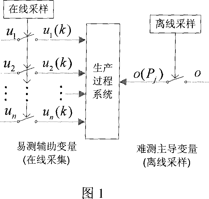
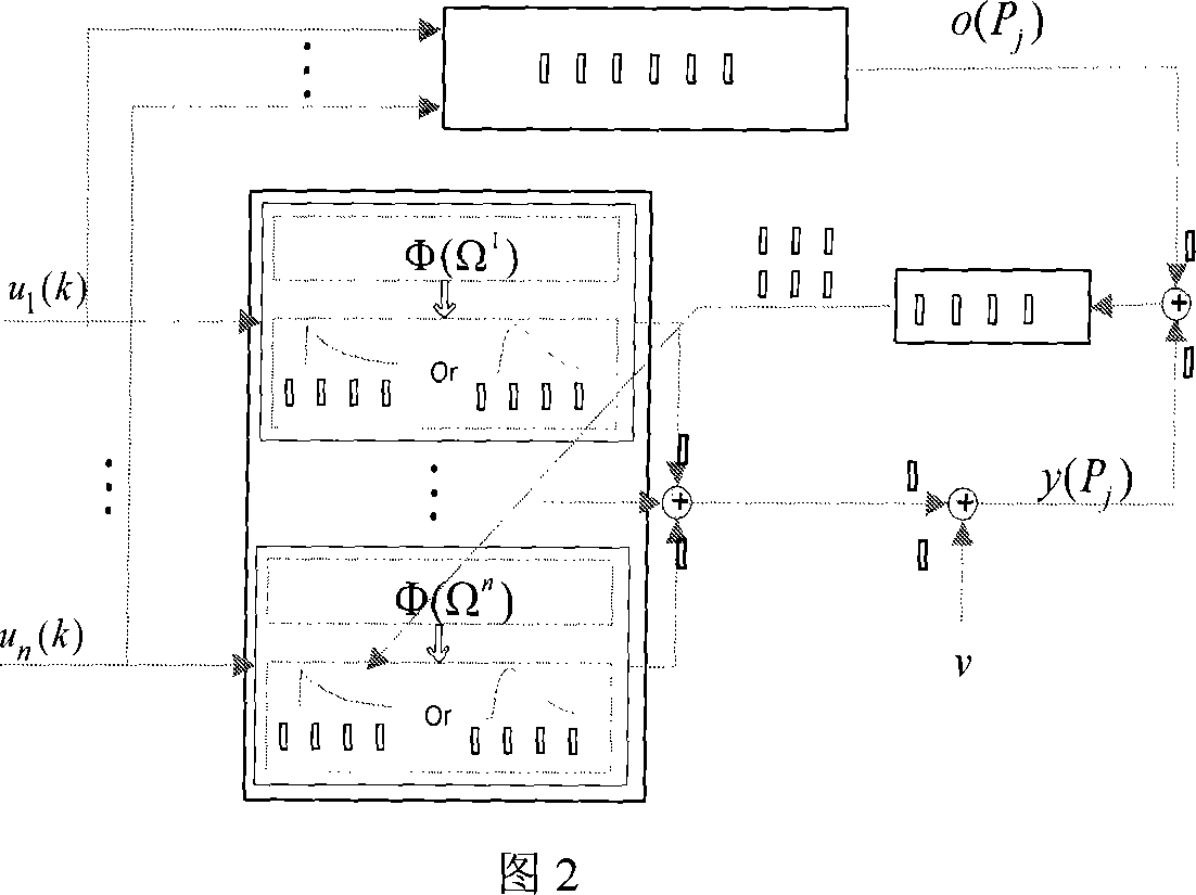
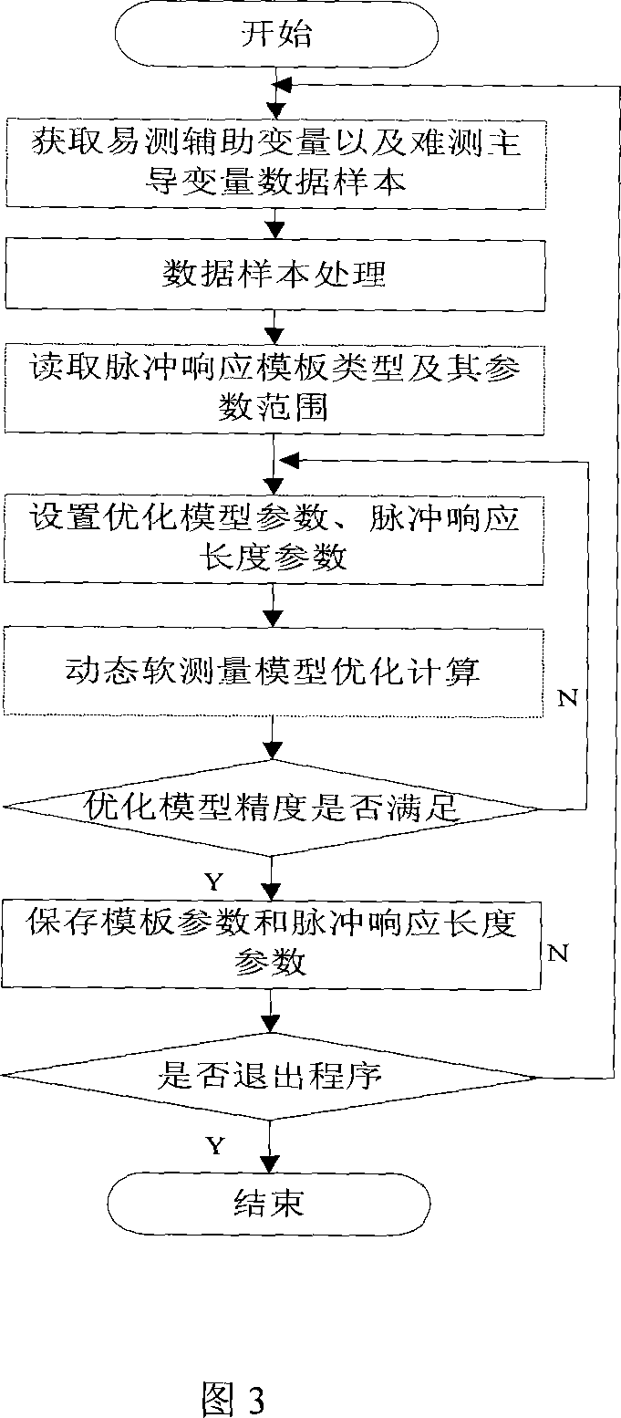
[0007] Purpose of the present invention: to propose a general dynamic soft sensor modeling method based on impulse response template and parameter optimization, to solve the online real-time measurement of important difficult-to-measure variables in the production process, and to overcome the above-mentioned background of existing soft sensor methods Problems that cannot or are difficult to promote and use

Method used


Image

  • Dynamic soft measuring and form establishing method base pulse response formwork and parameter optumization
  • Dynamic soft measuring and form establishing method base pulse response formwork and parameter optumization
  • Dynamic soft measuring and form establishing method base pulse response formwork and parameter optumization

Examples


Embodiment Construction

[0104] The present invention will be further described below in conjunction with a simulation example.

[0105] In order to be close to the actual production process, 2 inputs and 1 output are selected to generate a process system including two subsystems. The subsystems are second-order inertia plus lagging links. The model parameters of each subsystem are:

[0106] Ω 1 = { K p 1 , T 1 1 , T 2 1 , τ 1 1 } = { 120,15,12,2 } , Ω 2 = { K P 2 , T 1 2 , T 2 ...


PUM


Abstract

A modeling method of dynamic soft measurement based on pulse response template and parameter optimization includes setting up convolution mode based on pulse response principle, using pulse response parameter as main identification object, generating a set of pulse response template and template parameter constraint scope base on production process mechanism and utilizing optimized means to identify pulse response template parameter for finalizing optimization-solution of dynamic soft measurement model parameter.

Description

technical field [0001] The invention relates to a dynamic soft sensing method based on an impulse response template and an optimization method in the production process. This method is suitable for general soft sensor modeling of production process. Background technique [0002] With the development of production technology and the increasingly complex production process, in order to ensure the safety of production equipment, ensure product quality, and promote the wide application of direct closed-loop control of product quality, quality constraint and safety constraint control, product quality indicators are currently not visible. The important process variables of the production device put forward the requirement of real-time measurement or estimation of some important difficult-to-measure process variables. Due to technical or economical reasons, it is difficult to measure through online process instruments. Therefore, soft measurement and its application technology are...

Claims


Application Information

Patent Timeline
IPC IPC(8): G01D21/00G06N3/06
Inventor 黄德先杨庆吕文祥金以慧
Owner TSINGHUA UNIV
Learn More