Eureka AIR delivers breakthrough ideas for toughest innovation challenges, trusted by R&D personnel around the world.

Diaphragm pump of constant pressure type

A diaphragm pump and diaphragm valve technology, applied in the direction of pump, pump control, liquid variable capacity machinery, etc., can solve the problems of wasting water resources, inconvenience, and more reuse.

Inactive Publication Date: 2007-10-10
FOSHAN CITY SANJIAOZHOU ELECTRICAL TECH CO LTD
View PDF16 Cites 22 Cited by
  • Summary
  • Abstract
  • Description
  • Claims
  • Application Information

AI Technical Summary

Problems solved by technology

[0012] 1. Excess water from the pump head cover is discharged from the water pressure discharge port. Although it can be diverted into a general container for collection and reuse, it also increases the trouble for the user to reserve another container, or it cannot be used due to too much accumulated water. It is inconvenient to reuse all the water, but most consumers will choose to dump it directly, which will waste water resources virtually.
[0013] 2. When the excess water pressure passes through the water pressure discharge port of the pump head cover, it will often be accompanied by a large water flow noise, which will disturb the tranquility of the indoor environment at home

Method used


Image

  • Diaphragm pump of constant pressure type
  • Diaphragm pump of constant pressure type
  • Diaphragm pump of constant pressure type

Examples


Embodiment Construction

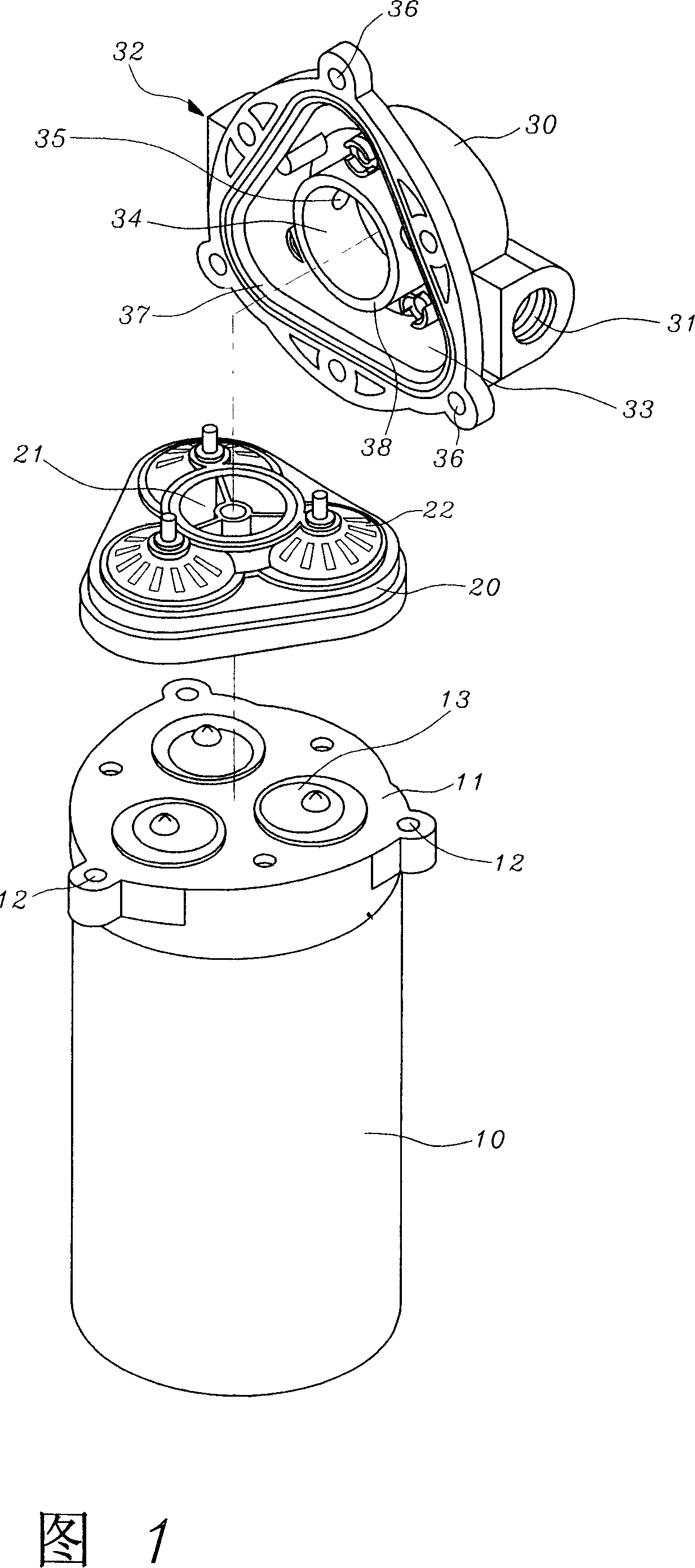
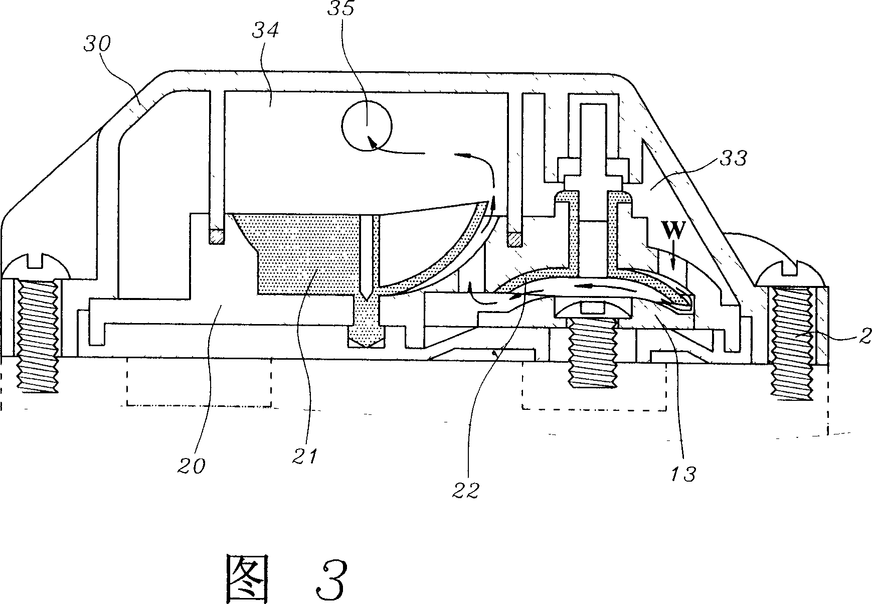
[0075] As shown in Figures 15 to 21, it is the first embodiment of the constant pressure diaphragm pump of the present invention. A constant pressure diaphragm pump of the present invention includes: a motor 10; (Not shown) the upper cover base 11 at the end, the upper cover base 11 is provided with a number of screw holes 12 on its periphery; one is pivoted in the upper cover base body 11, and is driven by the output shaft of the motor 10 and converted into an axial direction A number of reciprocating balance wheels 13; a diaphragm valve cover group 20 arranged on the upper cover seat 11, a high-pressure valve 23 is embedded in the center of the top surface, and a surrounding bottom surface of the high-pressure valve 23 is embedded There are several low-pressure valves 22; and a pump head cover 70, etc.; through the several screw holes 12 of the upper cover base 11 and the preset perforations 701 corresponding to the pump head cover 70, they are screwed together by bolts 2 Into o...


PUM


Abstract

The present invention provides a diaphragm pump of constant pressure type, mainly wherein a passage tube links between said pressure discharge port and said inlet port of said pump cover body; Thereby, the extra water pressure coming from said compressed chamber can be orderly discharged through said pressure discharge port, next guided through said passage tube to reach said inlet port, then directly flowed into said low pressure chamber; Therefore, a close water circulation loop of discharge pressure is built by means of connecting said compressed chamber, said pressure discharge port, said passage tube, said inlet port and said low pressure chamber; Thus, the present invention not only provides the function of keeping constant pressure, but also completely recycles the drained water by extra water pressure without any waste in water resource; Moreover, the present invention not only has the energy-saving effect in power consumption, but also has the environment-protecting effect in reducing operation noise; Thus, it is really an innovative invention with multiple practical effect.

Description

(1) Technical field [0001] The invention relates to a constant pressure diaphragm pump which is related to a pressure diaphragm pump dedicated to reverse osmosis purification, and in particular refers to a pressure diaphragm pump capable of venting the excessively high water pressure in the high-pressure water chamber of the pressure diaphragm pump to The pump head cover is outside of the body, and it is directly directed to the water inlet and then re-injected into the low pressure water chamber in the pump head cover to achieve the expected constant pressure value at the outlet of the pump head cover. (2) Background technology [0002] Currently known types of pressure diaphragm pumps used in reverse osmosis water filters, such as U.S. Patent Nos. 4396357, 4610605, 5476367, 5571000, 5615597, 5264464, 5649812, 5706715, 5791882, 5816133, 6048183, 6089838, 6299414, 6604909, 6840745 and No. 6892624, etc. have all been exposed, and the pressure diaphragm pump dedicated to the conven...

Claims


Application Information

Patent Timeline
IPC IPC(8): F04B43/02F04B49/08
Inventor 徐兆火
Owner FOSHAN CITY SANJIAOZHOU ELECTRICAL TECH CO LTD
Why Eureka
Eureka Blog
Learn More