
Laser processing method and processing device

A laser processing method and laser processing technology, which are applied to lasers, laser welding equipment, laser parts, etc., can solve the problems of time efficiency reduction and achieve high-precision processing

Inactive Publication Date: 2007-09-26
SUMITOMO HEAVY IND LTD
View PDF0 Cites 8 Cited by
  • Summary
  • Abstract
  • Description
  • Claims
  • Application Information

AI Technical Summary

Problems solved by technology

Although the opening shape is improved, the time efficiency of processing is reduced

Method used


Image

  • Laser processing method and processing device
  • Laser processing method and processing device
  • Laser processing method and processing device

Examples


Embodiment Construction

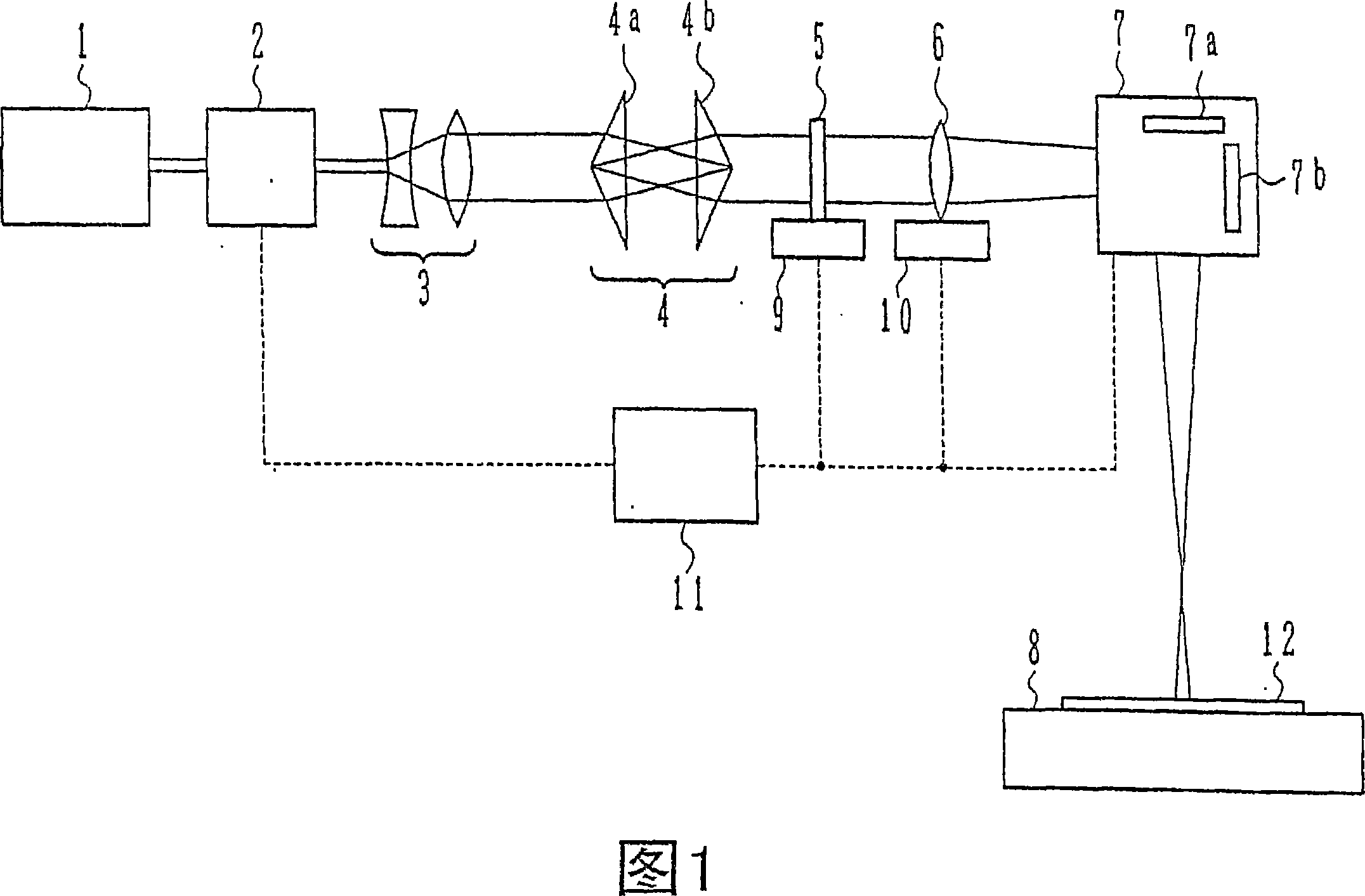
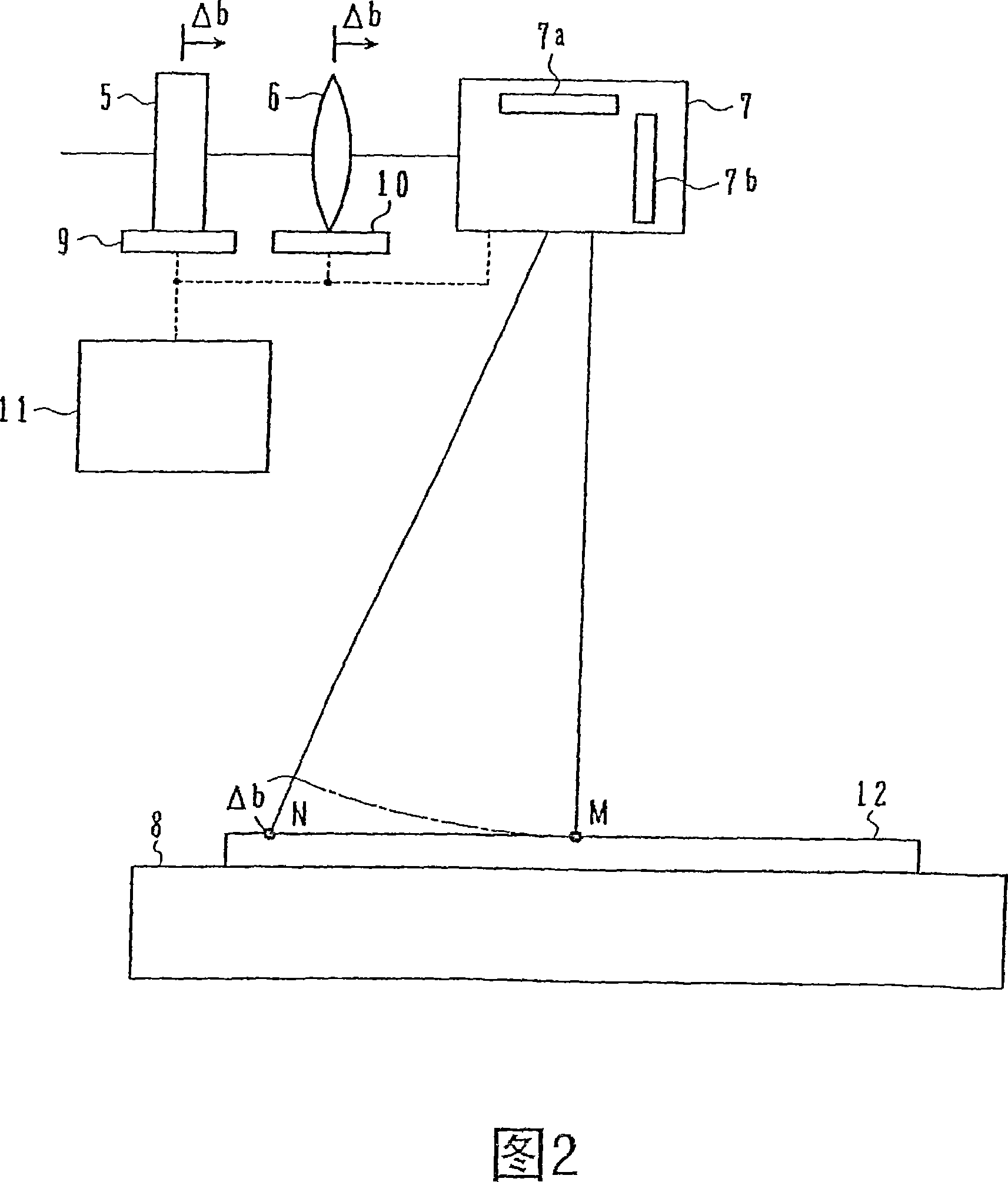
[0074] FIG. 1 is a schematic diagram of a laser processing apparatus for executing a laser processing method according to a first embodiment of the present invention.

[0075] In the laser light source 1, for example, a Nd:YAG laser oscillator including a wavelength conversion element emits a triple high-frequency wave (wavelength 355nm) of an Nd:YAG laser at a pulse energy of 1 mJ / pulse and a pulse width of 50 ns. The laser beam enters the conical optical system 4 after passing through the variable attenuator 2 that adjusts the pulse energy and the beam expander 3 that expands the beam diameter and emits it as parallel light. The conical optical system 4 includes a pair of conical lenses 4a, 4b. The pair of conical lenses 4 a and 4 b have, for example, the same shape, and are arranged such that their bottom surfaces face each other. The laser beam is incident on the conical lens 4a from the axial direction of the straight cone, so that the center of the beam section coincide...


PUM

PropertyMeasurementUnit
thicknessaaaaaaaaaa

Abstract

Laser beam is irradiated to a surface of a processing target after reforming a cross section of the laser beam with a mask having a pierced hole by concentrating the laser beam passing through the pierced hole by a lens to foreman image of the pierced hole of the mask on the surface of the processing target. The laser beam passing through the lens is scanned to move an irradiating position of the laser beam on the surface of the processing target, and the image of the pierced hole of the mask is formed on the surface of the processing target during the scanning for processing the processing target. A high quality laser process can be carried out.

Description

[0001] This application is a divisional application of the patent application with the application number "03820478.9" and the title of the invention "laser processing method and processing device" filed on August 29, 2003. technical field [0002] The present invention relates to a laser processing method and a laser processing device for processing an object to be processed by irradiating a laser beam. Background technique [0003] Fig. 9 is a schematic diagram showing a conventional laser processing apparatus for forming grooves. [0004] A pulsed laser beam is emitted from the laser light source 51 at a frequency of, for example, 1 kHz. After the pulse energy density of the beam cross section of the laser beam is made uniform (top flat) by a homogenizer 52, the beam cross section shape is shaped into a circle by, for example, a light shielding frame 53 having a circular through hole. After being reflected by the mirror 54 , it is incident on the substrate 56 through the...

Claims


Application Information

Patent Timeline
Patent Type & Authority Applications(China)
IPC IPC(8): B23K26/06B23K26/08B23K26/04G02B27/00B23K26/00
CPCB23K26/367B23K26/0652B23K26/0656B23K26/0648B23K26/381B23K26/385B23K26/066B23K26/364B23K26/382B23K26/389H01S3/10
Inventor 浜田史郎山本次郎山口友之
Owner SUMITOMO HEAVY IND LTD
Learn More