Ion mobility spectrometer

A technology of ion mobility and spectrometer, which is applied in the field of microfabricated FAIM spectrometer, field asymmetric ion mobility spectrometer, and performing ion mobility spectrometry

Inactive Publication Date: 2007-09-12
奥斯通有限公司
View PDF3 Cites 23 Cited by
  • Summary
  • Abstract
  • Description
  • Claims
  • Application Information

AI Technical Summary

Problems solved by technology

[0007] Although this arrangement offers the possibility of further miniaturization compared to traditional TOFIMS, the need to generate airflow requires the presence of pumps, baffles or the like whose use limits the lower limit of such devices. Dimensions of prior art

Method used


Image

  • Ion mobility spectrometer
  • Ion mobility spectrometer
  • Ion mobility spectrometer

Examples


Embodiment Construction

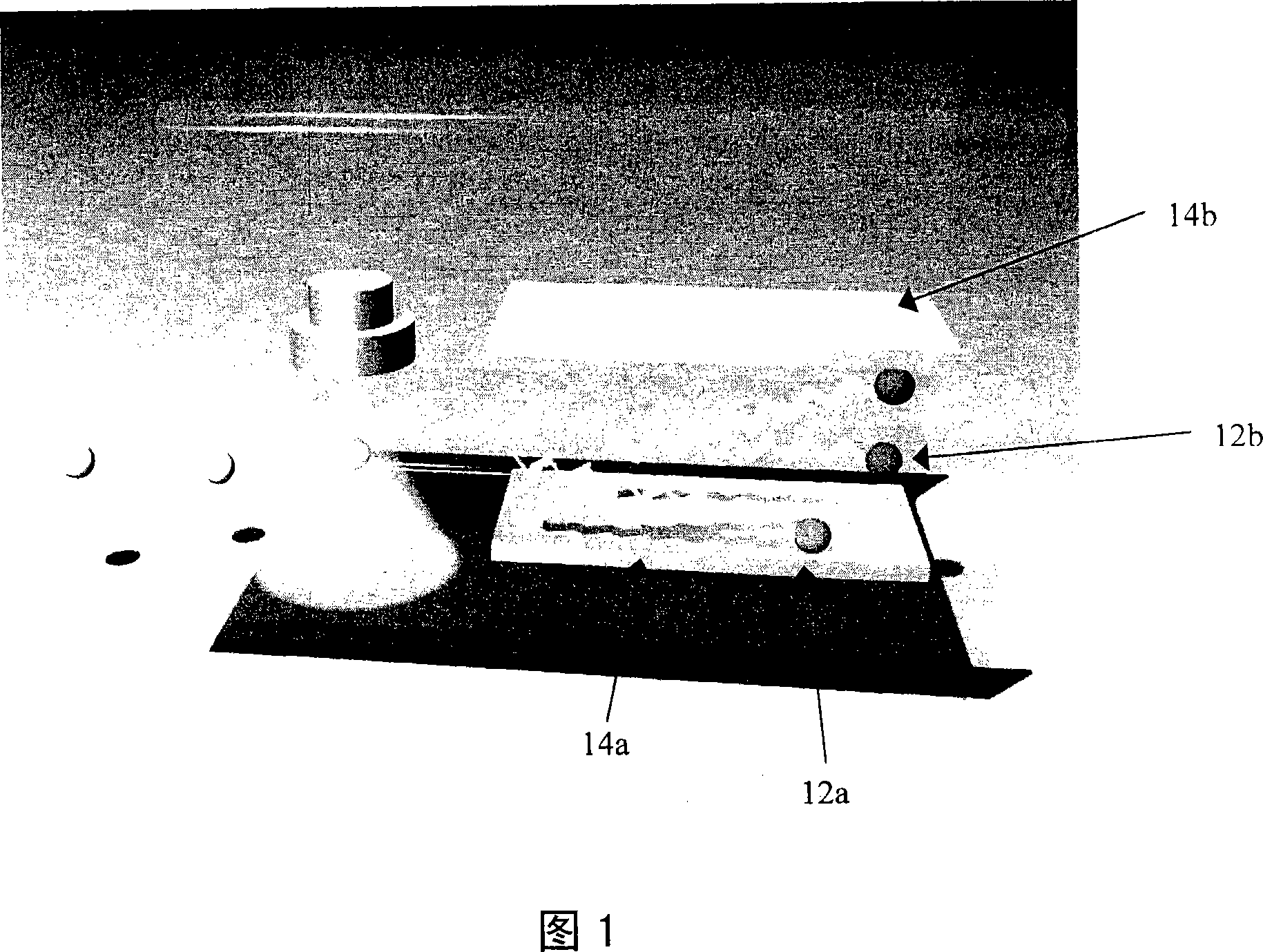
[0088] Figure 1 schematically shows the operation of a conventional FAIMS (Field Asymmetric Ion Mobility Spectroscopy). Air is drawn at atmospheric pressure into the reaction zone where the sample components are ionized. Between two metal electrodes 14a, 14b, one with a low voltage DC bias, and the other with a periodic high voltage pulse waveform, ions are blown onto a detector plate (not shown) where they hit the detector plate, and the current is recorded. The ions are driven rapidly towards one electrode during the pulse phase and slowly towards the opposite electrode between pulses. Some ions 12a hit the electrodes before reaching the detector plate; other ions 12b with appropriate differential mobility reach the end point, making it a differential mobility ion filter. A plot of the resulting current versus DC bias provides a characteristic differential ion mobility spectrum. The intensities of the peaks in the spectrum corresponding to the amount of charge represent t...


PUM


Abstract

An ion mobility spectrometer is described having an ion filter in the form of at least one ion channel having a plurality of electrodes. A time-varying electric potential applied to the conductive layers allows the filler to selectively admit ion species. The electric potential has a drive and a transverse component, and in preferred embodiments each of the electrodes is involved in generating a component of both the drive and transverse fields. The device may be used without a drift gas flow, Microfabrication techniques are described for producing microscale spectrometers, as are various uses of the spectrometer.

Description

technical field [0001] The present invention relates to an ion mobility spectrometer, and more particularly, to a field asymmetric ion mobility (FAIM) spectrometer. Certain aspects of the invention relate to a microfabricated FAIM spectrometer. Aspects of the invention also relate to methods of performing ion mobility spectrometry, and elements for such spectrometers. Background technique [0002] Ion mobility spectrometry is a general technique for detecting the presence of molecular species in gas samples. This technique has particular application in the detection of explosives, drugs and chemical agents in samples, but it is not limited to these applications. Portable detectors are commonly used in security screening and the defense industry. However, conventional portable devices are still relatively large. [0003] Ion mobility spectrometry is based on the differential movement of different ion species through an electric field to the detector; and, if at all, by ap...

Claims


Application Information

Patent Timeline
IPC IPC(8): H01J49/42G01N27/64B01D59/44
Inventor 保罗·博伊尔安德鲁·凯尔戴维鲁伊斯·阿隆索
Owner 奥斯通有限公司
Why Eureka
Try Eureka