
Numerical control method of die casting machine and numerical control die casting machine

A die-casting machine and industrial control technology, applied in the field of casting machinery, can solve the problems that the motor cannot control the angular displacement, angular velocity, complicated control mode, and difficult maintenance, etc., and achieve the effects of rich support software, safe and reliable transmission, and convenient installation and maintenance

Inactive Publication Date: 2007-09-12
SHANDONG KEHUI POWER AUTOMATION
View PDF0 Cites 7 Cited by
  • Summary
  • Abstract
  • Description
  • Claims
  • Application Information

AI Technical Summary

Problems solved by technology

[0002] The development trend of die-casting machines is all-electric drive. The latest all-electric die-casting machines are driven by AC servo motors, but there are disadvantages such as high price, complicated control methods, easy damage, and difficult maintenance. The most important thing is that the motor cannot control angular displacement, angular velocity

Method used


Image

  • Numerical control method of die casting machine and numerical control die casting machine
  • Numerical control method of die casting machine and numerical control die casting machine
  • Numerical control method of die casting machine and numerical control die casting machine

Examples


Embodiment 1

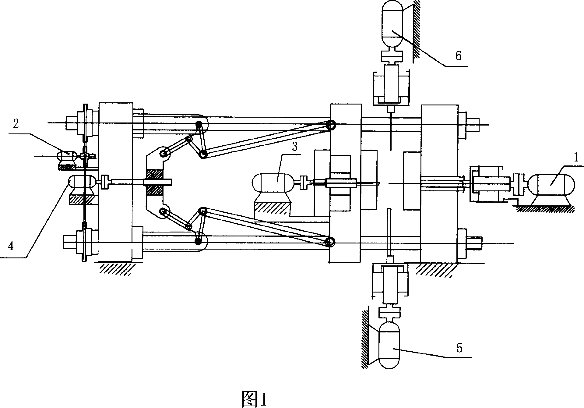
[0028]As shown in Figure 1: The motors of the injection device, mold adjusting device, ejector device, mold clamping device and inserting device of the CNC die-casting machine respectively adopt the switched reluctance speed control injection motor 1, the switch reluctance speed control mold control Motor 2, switched reluctance speed-regulating ejector motor 3, switched reluctance speed-regulating mold clamping motor 4 and switched reluctance speed-regulating plug-in motors 5,6. Switched reluctance speed-regulating injection motor 1, switched reluctance speed-regulating mold-adjusting motor 2, switched reluctance speed-regulating ejector motor 3, switched reluctance speed-regulating mold clamping motor 4 and switched reluctance speed-regulating core-inserting motor 5, 6 are respectively installed on the injection device, the mold adjustment device, the ejector device, the mold clamping device and the inserting core device.

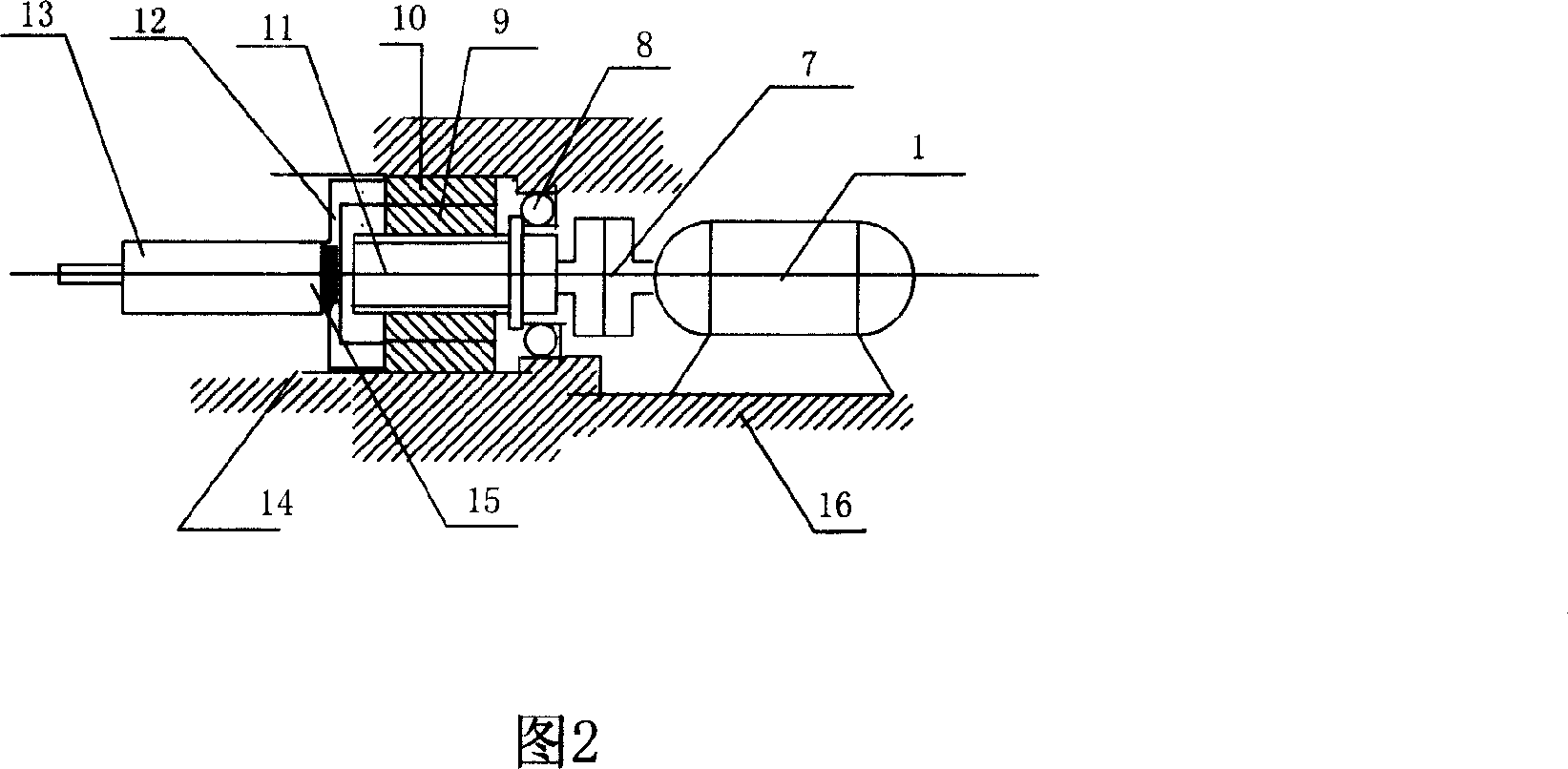
[0029] As shown in Figure 2: the injection device in...

Embodiment 2

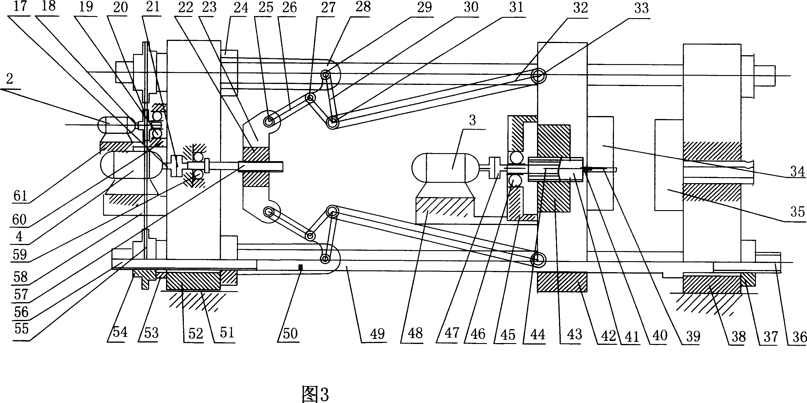
[0040] As shown in FIG. 7 : the difference from FIG. 3 of Embodiment 1 is that the rear connecting rod 64 in the clamping device connects the column pin 29 and the column pin 31 , and the middle rod 61 connects the column pin 31 and the column pin 25 . In the ejector device, the screw 65 is connected to the ejector rod 39 through the nut 66, the slider 67 and the connecting plate 69. The screw 65 and the nut 66 are driven by a screw pair, the nut 66 is connected with the slider 67 as a whole, and the slider 67 is slidably connected with the guide rail 68. The connecting plate 69 is integrally connected with the slider 68 , one end of the push rod 39 is integrally connected with the connecting plate 69 , and the guide rail 68 is fixed in the movable template 42 .

Embodiment 3

[0042] As shown in Figure 8: the difference from Figure 3 of Embodiment 1 is that the screw rod 70 and the nut 71 in the mold clamping device are driven by a screw pair, and the nut 71 is connected with the movable template 72 as a whole.


PUM


Abstract

The numerical control method of diecasting machine and the numerical control diecasting machine, belong to the casting mechanical domain. Including the input performance data, the labor-control the micro computer control motor movement, its characteristic lies in: The electromotor uses the switch magnetic resistance timing electromotor, controls movement of the switch magnetic resistance timing electromotor operation, after operation of the labor-control the micro computer according to the performance data provided by the input services, then the switch magnetic resistance timing electromotor drives diecasting machine movement. The numerical control method has can realize the microcomputer intelligence numerical control electric motor in angular displacement , angular speed as well as on-off, normal-reverse transfer, is easy to realize numerical control of each installment movement of the implementing agency in time,displacement ,speed and pressure, solves difficult technical problems which domain with this area since long ago. The numerical control diecasting machines have the merits of the structure simplicity, the lower cost and the higher working efficiency etc.

Description

technical field [0001] The invention relates to a numerical control method for a die casting machine and the numerical control die casting machine, belonging to the field of foundry machinery. Background technique [0002] The development trend of die-casting machines is all-electric drive. The latest all-electric die-casting machines are driven by AC servo motors, but there are disadvantages such as high price, complicated control methods, easy damage, and difficult maintenance. The most important thing is that the motor cannot control angular displacement, angular velocity. The various devices of the actuators of the die-casting machine require accurate and controllable displacement, speed, and pressure, frequent start and stop, and frequent reciprocating movements, which have become difficult technical problems in this field. Contents of the invention [0003] The technical problem to be solved by the present invention is: to provide a numerical control method for a di...

Claims


Application Information

Patent Timeline
IPC IPC(8): G05B19/18B22D17/32
Inventor 赵婷婷贾明全徐丙垠
Owner SHANDONG KEHUI POWER AUTOMATION
Learn More