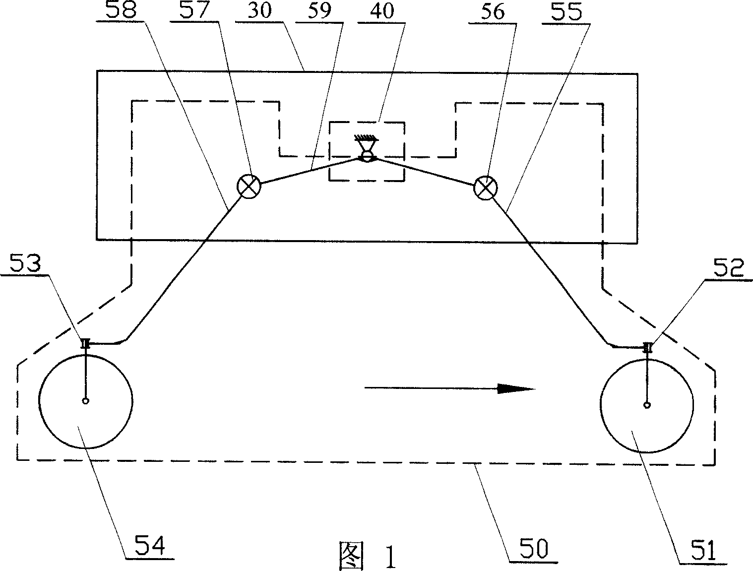
Four-wheel or six-wheel differential-torsion rod spring suspension type vehicle-carrying mechanism
A torsion bar spring and torsion bar technology, applied in the field of suspension vehicle-mounted mechanisms, can solve the problems of large number of wheels, large power consumption, and large overall mass, and achieve strong adaptive terrain change capabilities, reduced power consumption, The effect of controlling difficulty reduction
- Summary
- Abstract
- Description
- Claims
- Application Information
AI Technical Summary
Problems solved by technology
Method used
Image
Examples
specific Embodiment approach 1
[0007] Specific Embodiment 1: This embodiment is described with reference to FIGS. 1 to 4 . This embodiment is composed of a main vehicle body 30 , a four-wheel or six-wheel independent suspension mechanism and a differential device 40 ; the differential device 40 is arranged on the main vehicle body 30 The inside of the four-wheel independent suspension mechanism is composed of two one-sided two-wheel independent suspension mechanisms 50, and the two one-sided two-wheel independent suspension mechanisms 50 are respectively arranged on the left and right sides of the main vehicle body 30; The six-wheel independent suspension mechanism is composed of two unilateral three-wheel independent suspension mechanisms 60, and the two unilateral three-wheel independent suspension mechanisms 60 are respectively arranged on the left and right sides of the main vehicle body 30, and the differential device 40 They are fixedly connected with two unilateral two-wheel independent suspension mec...
specific Embodiment approach 2
[0008] Embodiment 2: This embodiment is described in conjunction with FIG. 2 and FIG. 4 . The differential device 40 of this embodiment is composed of a first bevel gear 41 , a second bevel gear 42 , a third bevel gear 43 , a fourth bevel gear 44 , and a housing. body 45, the first extension shaft 46, the second extension shaft 47, the third short shaft 48 and the fourth short shaft 49; The first bevel gear 41 meshes with the third bevel gear 43 and the fourth bevel gear 44 respectively, the third bevel gear 43 is affixed to the inner end of the third short shaft 48, the fourth bevel gear 44 is connected to the fourth short shaft 49 The inner end of the third short shaft 48 and the outer end of the fourth short shaft 49 are respectively vacantly sleeved on the housing 45, installed in the housing 45 and affixed to the inner end of the second extension shaft 47 The second bevel gear 42 meshes with the third bevel gear 43 and the fourth bevel gear 44 respectively, and the first ...
specific Embodiment approach 3
[0009] Specific Embodiment Three: This embodiment is described in conjunction with Fig. 1 and Fig. 2. Each one-sided two-wheel independent suspension mechanism 50 of this embodiment is respectively composed of a first front drive wheel 51, a first front steering motor 52, a first front Suspension bar 55, first front torsion bar spring 56, first differential sway bar 59, first rear torsion bar spring 57, first rear suspension bar 58, first rear steering motor 53, first rear drive wheel 54 Composition; the front side of the first front suspension rod 55 is provided with a first front steering motor 52, the output end of the first front steering motor 52 is hinged with the first front driving wheel 51, and the upper end of the first front suspension rod 55 It is affixed to the movable end of the first front torsion bar spring 56, the fixed end of the first front torsion bar spring 56 is affixed to the front end of the first differential swing bar 59, and the rear end of the first ...
PUM
 Abstract
Description
Claims
Application Information
 - R&D
- Intellectual Property
- Life Sciences
- Materials
- Tech Scout
- Unparalleled Data Quality
- Higher Quality Content
- 60% Fewer Hallucinations
Browse by: Latest US Patents, China's latest patents, Technical Efficacy Thesaurus, Application Domain, Technology Topic, Popular Technical Reports.
© 2025 PatSnap. All rights reserved.Legal|Privacy policy|Modern Slavery Act Transparency Statement|Sitemap|About US| Contact US: help@patsnap.com


