Variable compression ratio internal combustion engine
A technology of internal combustion engine and compression ratio, applied in internal combustion piston engine, combustion engine, fuel system, etc., can solve the problem of obtaining engine performance and so on
- Summary
- Abstract
- Description
- Claims
- Application Information
AI Technical Summary
Problems solved by technology
Method used
Image
Examples
no. 1 example
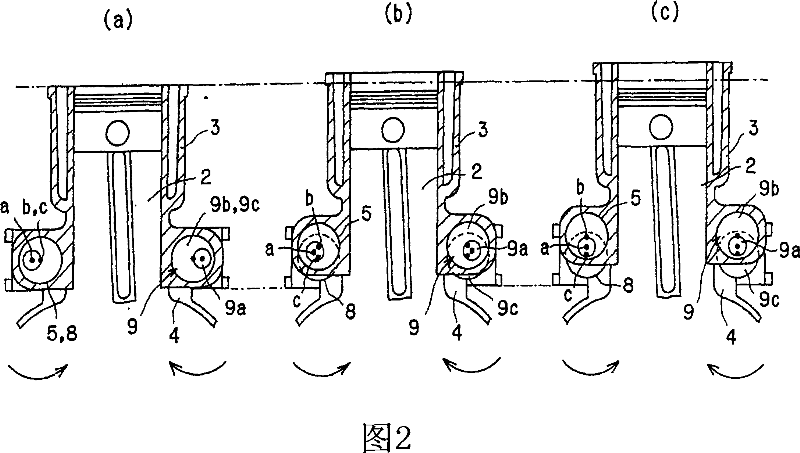
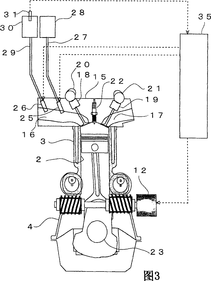
[0045] The internal combustion engine 1 to be described below is a variable compression ratio internal combustion engine in which the compression ratio is changed by moving the position of the cylinder block 3 having the cylinder 2 in the direction of the central axis of the cylinder 2 relative to the crankcase 4 in which the piston and the crankcase 4 Associated.
[0046] First, the structure of a variable compression ratio internal combustion engine according to the present embodiment will be described with reference to FIG. 1 . As shown in FIG. 1, the cylinder block 3 has a plurality of protrusions formed on both lower sides thereof, each protrusion having a bearing receiving hole 5 formed therein, the bearing receiving hole 5 being cylindrical and vertical Extends in the axial direction of the cylinder 2 and parallel to the arrangement direction of the plurality of cylinders 2 . The bearing receiving holes 5 are arranged coaxially on one side, and a pair of axes of the be...
no. 2 example
[0081] A second embodiment of the present invention will be described below. In the second embodiment, a description is made regarding the compression ratio control of an internal combustion engine 1 equipped with a hydrogen fuel injection valve 26 for injecting hydrogen as fuel into the intake port 16, and The direct-injection hydrogen fuel injection valve 33 is used to directly inject hydrogen as fuel into the cylinder 2 .
[0082]FIG. 7 is a cross-sectional view showing the detailed structure of the internal combustion engine 1 of the present invention. In this embodiment, a direct injection type hydrogen fuel injection valve 33 is provided on the top wall of the combustion chamber of the internal combustion engine 1 . The direct-injection hydrogen fuel injection valve 33 is connected to a direct-injection hydrogen supply pipe 34 . The other end of the direct injection hydrogen supply pipe 34 is connected with the hydrogen supply pipe 29 . In the middle of the direct inj...
no. 3 example
[0090] A third embodiment of the present invention is described below. In the third embodiment, a control will be described in which when the internal combustion engine 1 uses hydrogen as fuel and the NO of the internal combustion engine 1 X Emissions greater than limit NO X When the emission amount is exceeded, the air-fuel ratio is made leaner or richer according to the air-fuel ratio of the internal combustion engine 1 at that time, and the compression ratio is lowered to reduce NO X emissions. The detailed structure of this internal combustion engine 1 is the same as that shown in Fig. 3, and thus its description is omitted.
[0091] FIG. 8 is a graph showing the air-fuel ratio and NO in the internal combustion engine 1 when hydrogen is used as fuel. X A graph of the relationship between emissions. As shown in Figure 8, when hydrogen is used as fuel, NO X Emissions increased and at one point reached their peak. And as the air-fuel ratio further changes to the rich si...
PUM
 Abstract
Description
Claims
Application Information
 - R&D
- Intellectual Property
- Life Sciences
- Materials
- Tech Scout
- Unparalleled Data Quality
- Higher Quality Content
- 60% Fewer Hallucinations
Browse by: Latest US Patents, China's latest patents, Technical Efficacy Thesaurus, Application Domain, Technology Topic, Popular Technical Reports.
© 2025 PatSnap. All rights reserved.Legal|Privacy policy|Modern Slavery Act Transparency Statement|Sitemap|About US| Contact US: help@patsnap.com


