
Continuously calibrated magnetic field sensor

A magnetic field sensor and sensor technology, applied in the field of magnetic field sensors, can solve the problems such as the difficulty of removing the reference signal, no intention to measure high-frequency current, limited measurement bandwidth, etc.

Active Publication Date: 2010-06-09
莱姆电子(中国)有限公司
View PDF6 Cites 0 Cited by
  • Summary
  • Abstract
  • Description
  • Claims
  • Application Information

AI Technical Summary

Problems solved by technology

These solutions for removing the reference signal are difficult to implement and are subject to some variation due to temperature and other factors
A further disadvantage in the current sensor described in US 4,751,733 is its limited measurement bandwidth, it is practically not intended to measure high frequency currents e.g. at frequencies up to 100KHz

Method used


Image

  • Continuously calibrated magnetic field sensor
  • Continuously calibrated magnetic field sensor
  • Continuously calibrated magnetic field sensor

Examples


Embodiment Construction

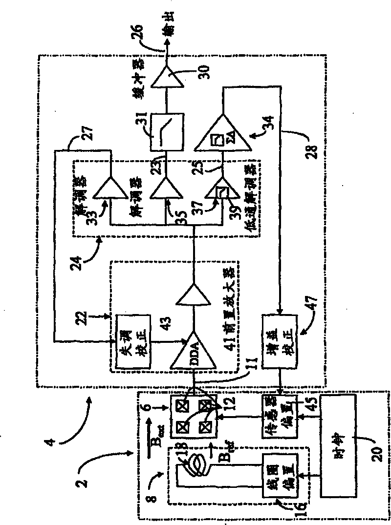
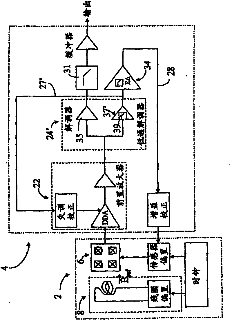
[0031] see first Figures 1a to 3 , the electromagnetic field sensor according to the present invention generally includes a magnetic field sensitive circuit 2 and a signal processing circuit 4 . The magnetic field sensitive circuit 2 includes a magnetic field sensitive unit 6 , a reference magnetic field generator 8 and a gain correction input 10 .

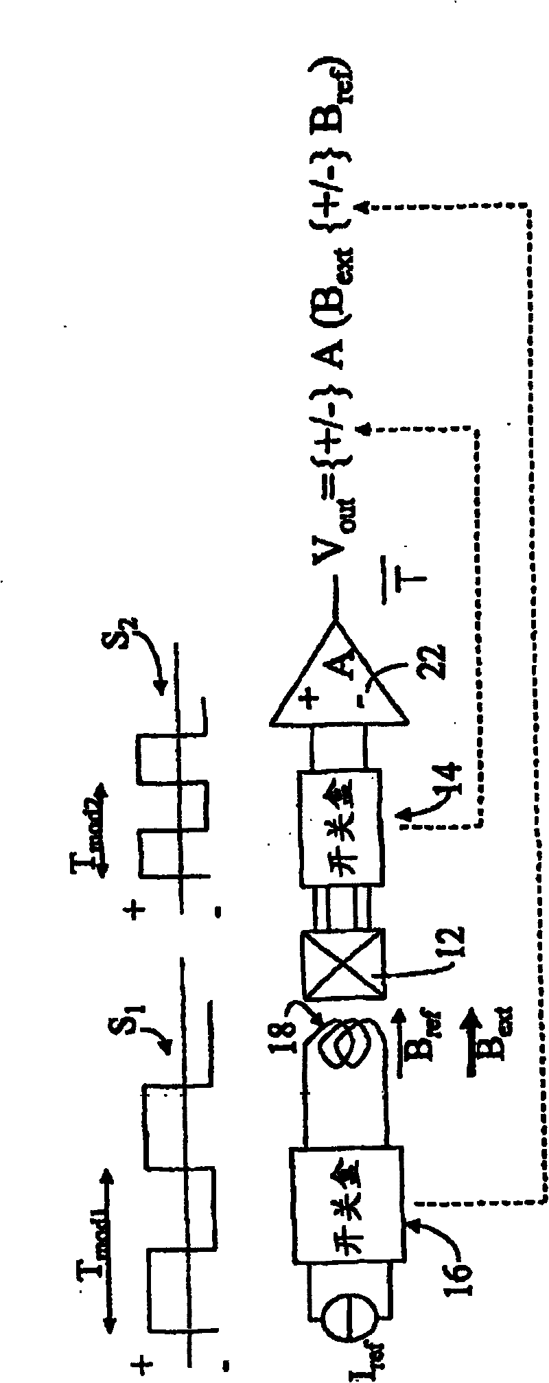
[0032] The magnetic field sensitive unit 6 may include one or more magnetic field sensitive elements 12, such as a Hall effect sensor or Hall effect sensor array formed in an integrated circuit known in the art, and the magnetic field sensitive unit 6 further includes a sensor for modulating each magnetic field sensitive Element 12 outputs modulator 14 of the signal. The reference magnetic field generator 8 includes a modulated reference current input 16 driving one or more reference coils 18 for generating a reference magnetic field Bref to be applied to each magnetic field sensitive element 12 . The frequency of driving the r...


PUM


Abstract

A magnetic field sensor comprises a reference magnetic field generator (8), a magnetic field sensing cell (6) including Hall effect sensing elements (12), and a signal processing circuit (4) connectedto the output (11) of the magnetic field sensing cell and comprising one or more feedback lines (27, 28) for correcting error fluctuations in the transfer characteristic of the magnetic field sensor.The reference magnetic field generator is adapted to generate a frequency modulated reference magnetic field. The signal processing circuit further includes a modulator connected to the magnetic field sensing cell, adapted to modulate the output signal thereof at a frequency different from the modulation frequency of the reference magnetic field generator.

Description

technical field [0001] The present invention relates to continuously calibrated magnetic field sensors for compensating fluctuations in transmission characteristics due to factors such as temperature, ageing, mechanical stress and voltage imbalance. In particular, the gain of the sensor is continuously calibrated in order to keep it constant. The invention also relates to a current sensor for measuring the current flowing in an external electrical conductor by means of a continuously calibrated magnetic field sensor. Background technique [0002] Multiple magnetic field sensors are calibrated during the manufacturing process to compensate for magnetic field sensor gain and voltage offset and temperature drift of signal processing circuits. However, some factory calibration values ​​are not able to compensate for fluctuations in sensor transfer characteristics originating from factors such as mechanical stress and aging of the various sensor elements and circuits. The latte...

Claims


Application Information

Patent Timeline
Patent Type & Authority Patents(China)
IPC IPC(8): G01R33/07
CPCG01R33/07G01R33/075G01R33/0035G01R15/20
Inventor 马克·帕斯特尔休伯特·布兰查德马赫·卡亚尔
Owner 莱姆电子(中国)有限公司
Learn More