


Quick Research
Generate reliable direction feasibility study reports for your R&D in just a few steps.

Technical Q&A
Discover and master advanced knowledge NOW. Basics, ideas, possibilities, all at once.

Find Solutions
As an expert in R&D theories, this can generate solutions to your technical problems instantly.

Evaluate Feasibility
Analyze your overall solution with one click, know your potential R&D risks in advance.

Monitor Landscape
Get weekly tech updates, stay abreast of the latest tech innovations and key insights.
Throwing mechanism for cabin cleaning vehicle
A technology of material belt and motor bracket, which is applied in the direction of throwing machine, mechanical equipment, loading/unloading, etc., can solve the problems of high labor intensity, injury and death of cleaning workers.
- Summary
- Abstract
- Description
- Claims
- Application Information
AI Technical Summary
Problems solved by technology
Method used
Image


Examples
Embodiment 1
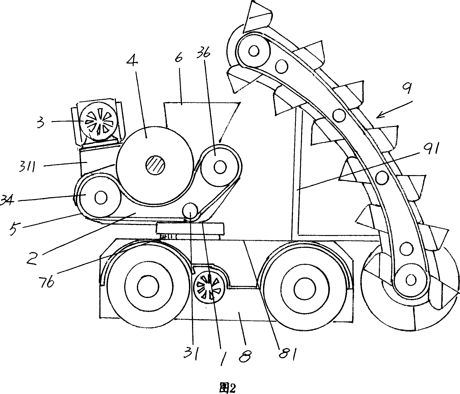
[0019] 1 , the applicant provides a base 1 that can be directly fixed to the chassis cover 81 of the chassis 8 of the cleaning vehicle, and a bracket 2 is extended on both symmetrical sides of the base 1 . Taking the position state shown in the figure as an example, a motor bracket 311 is extended on the left end top of a pair of brackets 2, and the motor 31 as the power transmission device 3 recommended by the present invention is fixed on the motor bracket 311, and the motor bracket 311 The left and right sides are not closed, so as to constitute the discharge port 3111. Motor 31 is controlled by PLC (programmable logic controller), and when it was working, the small sprocket 32 fixed on the shaft end of its power output shaft drove the large sprocket 35 to rotate through the chain 33, because the large sprocket 35 was fixed One of the shaft ends of the driving roller 34, so the driving roller 34 rotates, and the driving roller 34 is pivoted with a pair of brackets 2 throu...
Embodiment 2
[0021] Still in conjunction with Fig. 1, a rotary device 7 is added at the bottom of the base 1, specifically, the base 1 is fixed to the screw hole 761 on the rotary gear 76 as the rotary device 7 through the screw 11, and the rotary gear 76 is matched with the bearing 77 , and the bearing 77 is arranged on the chassis cover 81 of the chassis 8 of the cleaning vehicle by the bearing fixing ring 771, and the screw hole 7711 is preset on the bearing fixing ring 771, and it is fixed with the chassis cover 81 with screws. As the rotary motor 71 controlled by PLC rotates clockwise or counterclockwise, the small rotary sprocket 72 fixed on the power output shaft of the motor drives the large rotary sprocket 74 to move through the rotary chain 73 . The sprocket shaft 741 of the large rotary sprocket 74 is pivotally placed on the chassis cover 81 through the shaft seat 7411. With the movement of the large rotary sprocket 74, the small rotary gear 75 fixed on the sprocket shaft 741 dri...
Embodiment 3
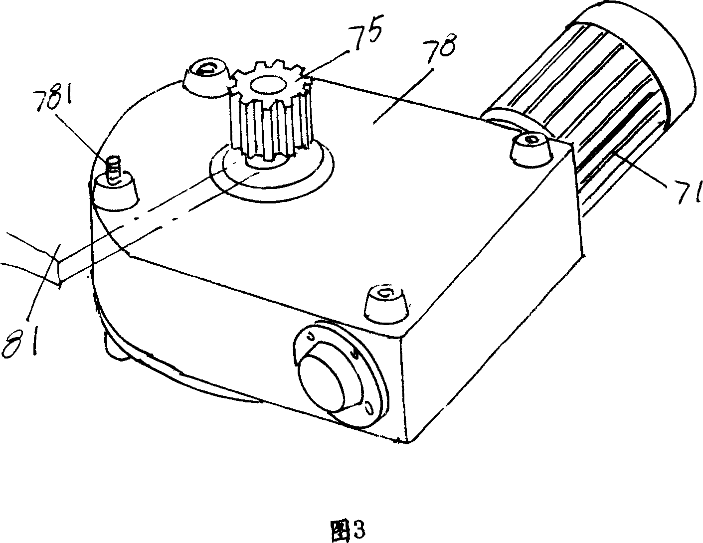
[0023] Please refer to Fig. 2, the applicant has provided another structural form of the rotary device 7, the reducer 78 is fixed on the chassis cover 81 of the chassis 8 with screws 781, the rotary pinion 75 is connected with the reducer 78 and connected with the rotary large Gear 76 meshes. Along with motor 71 work, after speed reducer 78 decelerates, is driven by rotary pinion gear 75 and rotates bull gear 76. It can be seen that the overall structure of the rotary device 7 disclosed in this embodiment is simpler than that in Embodiment 2.
[0024] Application example;
[0025] Please in conjunction with Fig. 3, the proposed structure of the present invention is configured on the chassis cover 81 of the chassis 8 by the structure of embodiment 1 or 2 or 3, and, on the chassis 8, the material taking mechanism 9 is carried by a bracket 91, and they are jointly constituted as Clearance truck. The applicant briefly describes the working principle of the present invention in ...
PUM
 Abstract
Description
Claims
Application Information
 - R&D Engineer
- R&D Manager
- IP Professional
- Industry Leading Data Capabilities
- Powerful AI technology
- Patent DNA Extraction
Browse by: Latest US Patents, China's latest patents, Technical Efficacy Thesaurus, Application Domain, Technology Topic, Popular Technical Reports.
© 2024 PatSnap. All rights reserved.Legal|Privacy policy|Modern Slavery Act Transparency Statement|Sitemap|About US| Contact US: help@patsnap.com