Test method of RF mark

A technology of radio frequency tags and testing methods, applied in the field of testing, to achieve the effect of ensuring read and write performance

Active Publication Date: 2007-08-08
SHANGHAI HUASHEN INTELLIGENT IC CARD APPL SYST
View PDF0 Cites 9 Cited by
  • Summary
  • Abstract
  • Description
  • Claims
  • Application Information

AI Technical Summary

Problems solved by technology

[0002] When the RF tag chip is packaged in the antenna, the resonant peak value and bandwidth are important indicators to measure the quality of the RF tag package. The spectrum analyzer with frequency sweep function can only measure the static peak value and bandwidth of the RF tag.

Method used


Image

  • Test method of RF mark
  • Test method of RF mark

Examples


Embodiment Construction

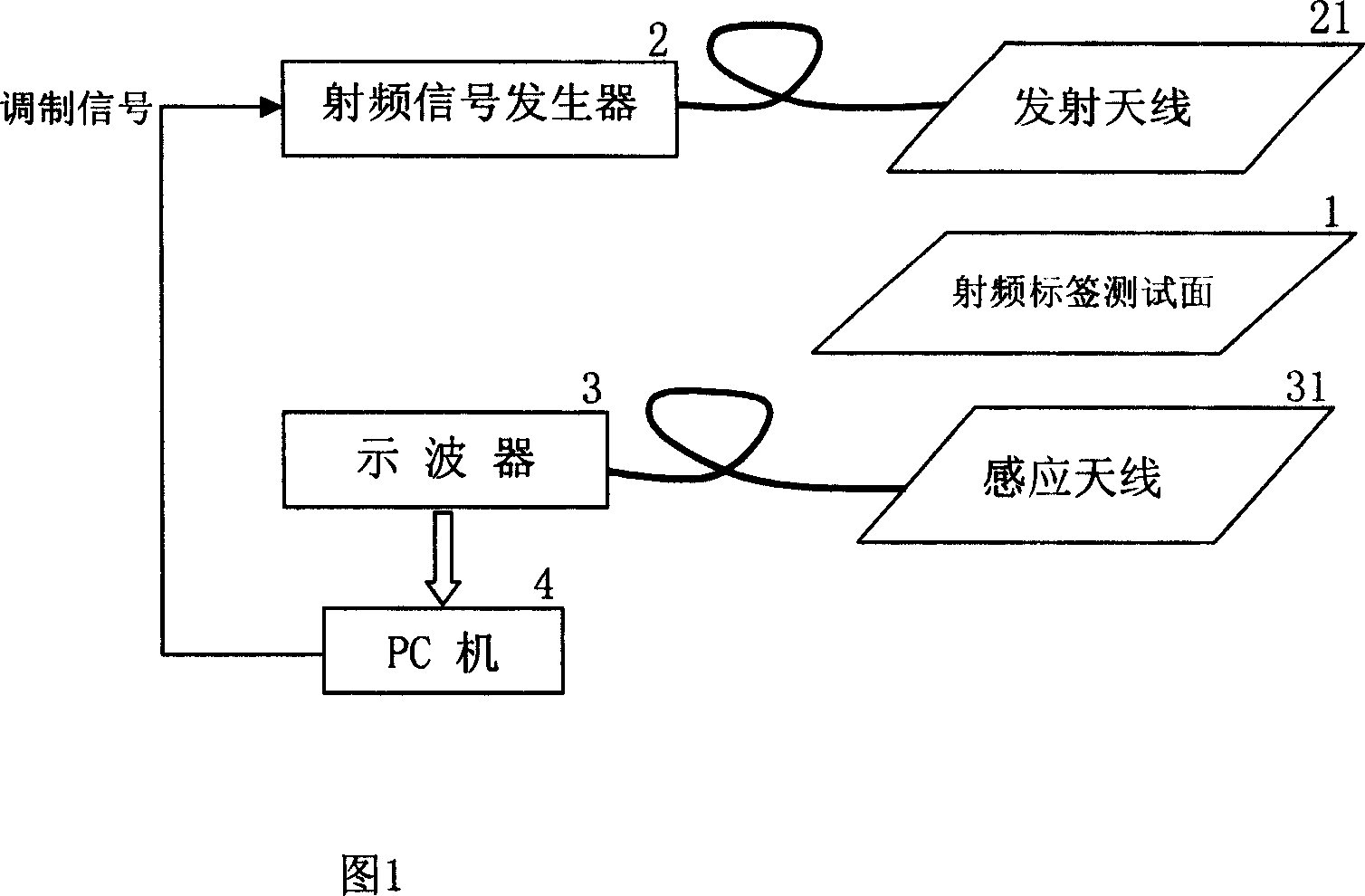
[0020] Referring to Fig. 1 and Fig. 2, the present invention will be further described.

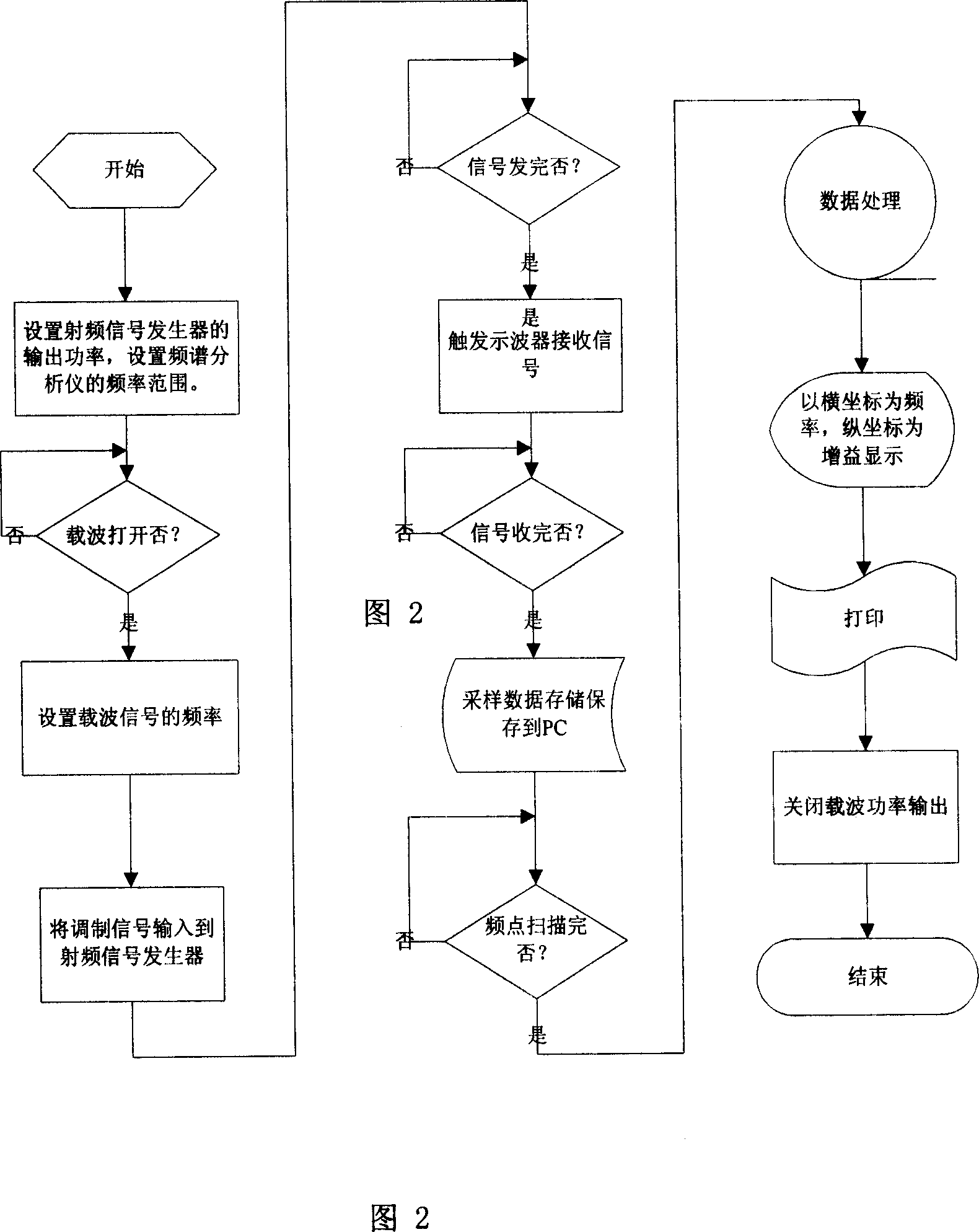
[0021] As shown in Fig. 1, the principle block diagram of the present invention and Fig. 2, the working flow chart of the present invention, the whole test steps and process are described by taking the test of the 13.56MHz radio frequency tag 1 conforming to the ISO / IEC15693 protocol as an example.

[0022] The working frequency of the 13.56MHz RF tag 1 is specified within the range of 13.56MHz±7KHz. When the antenna of the RF tag 1 is packaged, the resonant frequency often has a large deviation from the actual need, which will affect the identification distance of the RF tag 1. . The frequency test range we set is 10MHz to 20MHz, and the frequency step interval is 100KHz, so there are 100 test points in total, and the data of the whole test is completed by the PC 4 .

[0023] This test method includes the following steps:

[0024] 1) The PC 4 sends instructions to the RF signal generat...


PUM


Abstract

It is an RFID testing method, using the determined coding instructions to modulate the RF signal generator carrier, assuring that under the rated output power, in accordance with RFID working frequency range to scan, and meanwhile modulating the carrier signal according to the RFID protocol, the oscillograph sends the time-domain signal peak received by its sensing antenna to PC, and PC converts the time-domain signal frequency into the frequency-domain signal, and thus it can detect RFID dynamic resonance peak and bandwidth, ensuring the reading and writing performance after RFID mass-production.

Description

technical field [0001] The invention relates to a testing method, in particular to a testing method of radio frequency tags. Background technique [0002] When the RF tag chip is packaged in the antenna, the resonance peak and bandwidth are important indicators to measure the quality of the RF tag package. The spectrum analyzer with sweep function can only measure the static peak value and bandwidth of the RF tag. Contents of the invention [0003] The technical problem of the present invention is to provide a testing method capable of measuring the dynamic resonance peak value and bandwidth of the radio frequency tag. [0004] In order to solve the technical problems above, the present invention provides a kind of testing method of radio frequency label, and it comprises the following steps: [0005] 1) A radio frequency annunciator, which maintains a constant power output and sends it to the transmitting antenna; [0006] 2) Modulating the determined coding instruction...

Claims


Application Information

Patent Timeline
IPC IPC(8): G01R31/28G06K7/00
Inventor 王洁民王伟沈甦郭海岛
Owner SHANGHAI HUASHEN INTELLIGENT IC CARD APPL SYST
Why Eureka
Try Eureka