
Residual heat generating system used for new type nonaqueous cement production line

A dry-process cement and waste heat power generation technology, which is applied in cement production, clinker production, waste heat treatment, etc., can solve problems such as air leakage, dust accumulation in heat exchangers, and uneven air distribution

Active Publication Date: 2007-08-08
BEIJING LIULIHE CEMENT +1
View PDF0 Cites 23 Cited by
  • Summary
  • Abstract
  • Description
  • Claims
  • Application Information

AI Technical Summary

Problems solved by technology

[0002] At present, the pure low-temperature waste heat power generation system of the new dry-process cement production line commonly used at home and abroad is to use the hot air drawn from the cooling air outlet of the grate cooler at the kiln head of the existing cement production line and the flue gas discharged from the first-stage preheater. The heat is converted into the internal energy of water vapor through the waste heat boiler, and the steam-water circulation system of the 1950s is used to drive the turbine generator to generate electricity; The exhausted high-temperature flue gas has not been classified and utilized, and there are still problems such as air leakage, uneven air distribution, dust accumulation on the heat exchanger, and fouling. Therefore, only steam with low pressure and low temperature parameters can be generated, and the steam turbine generator Low efficiency and low power generation per unit of thermal energy; the power generation capacity per ton of clinker using the pure low-temperature waste heat of this new type of dry process cement kiln is generally 26-28kwh, and the power generation capacity per ton of clinker with advanced Japanese technology can only reach 33 ~38kwh

Method used


Image

  • Residual heat generating system used for new type nonaqueous cement production line
  • Residual heat generating system used for new type nonaqueous cement production line
  • Residual heat generating system used for new type nonaqueous cement production line

Examples


Embodiment Construction

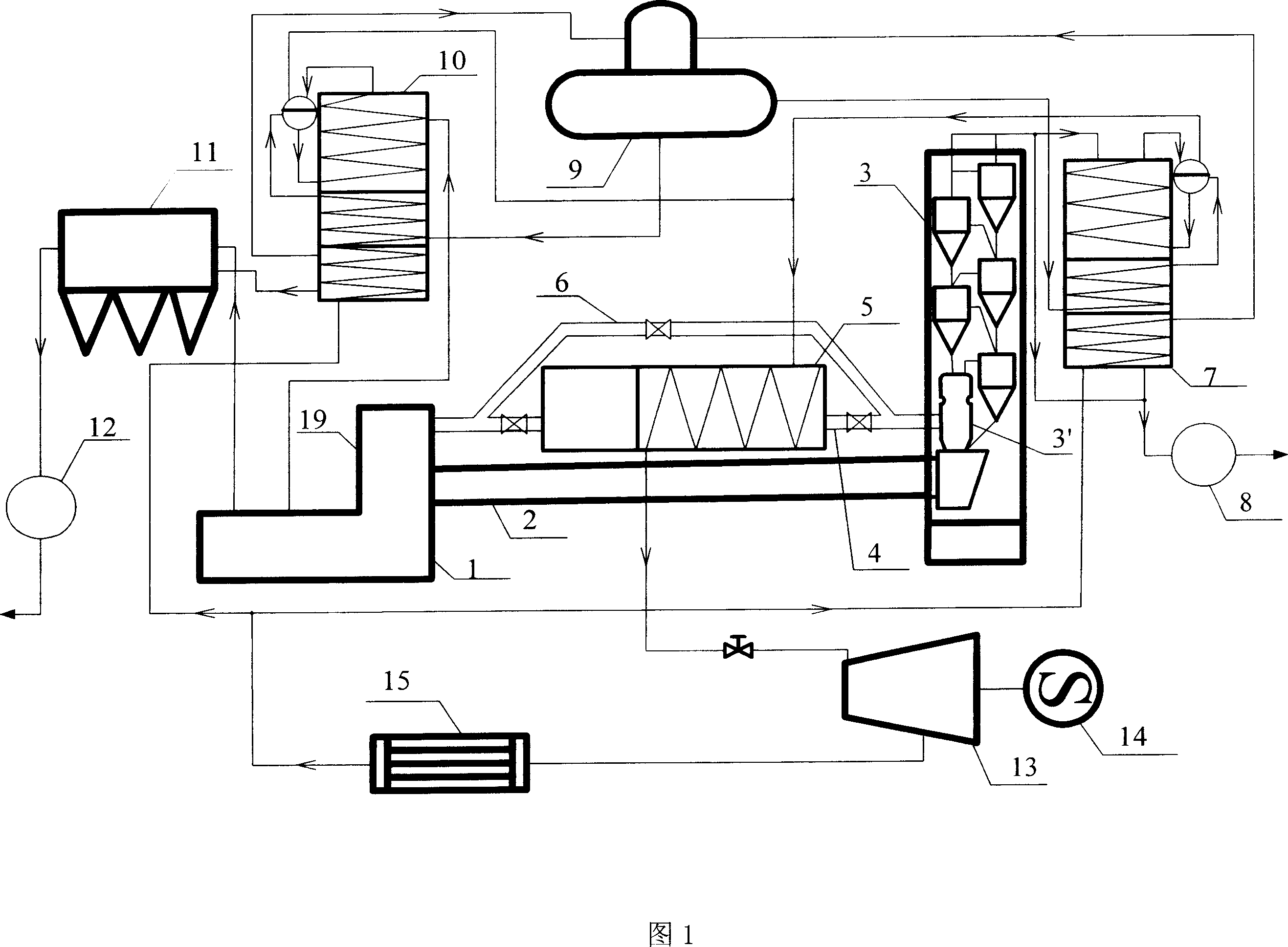
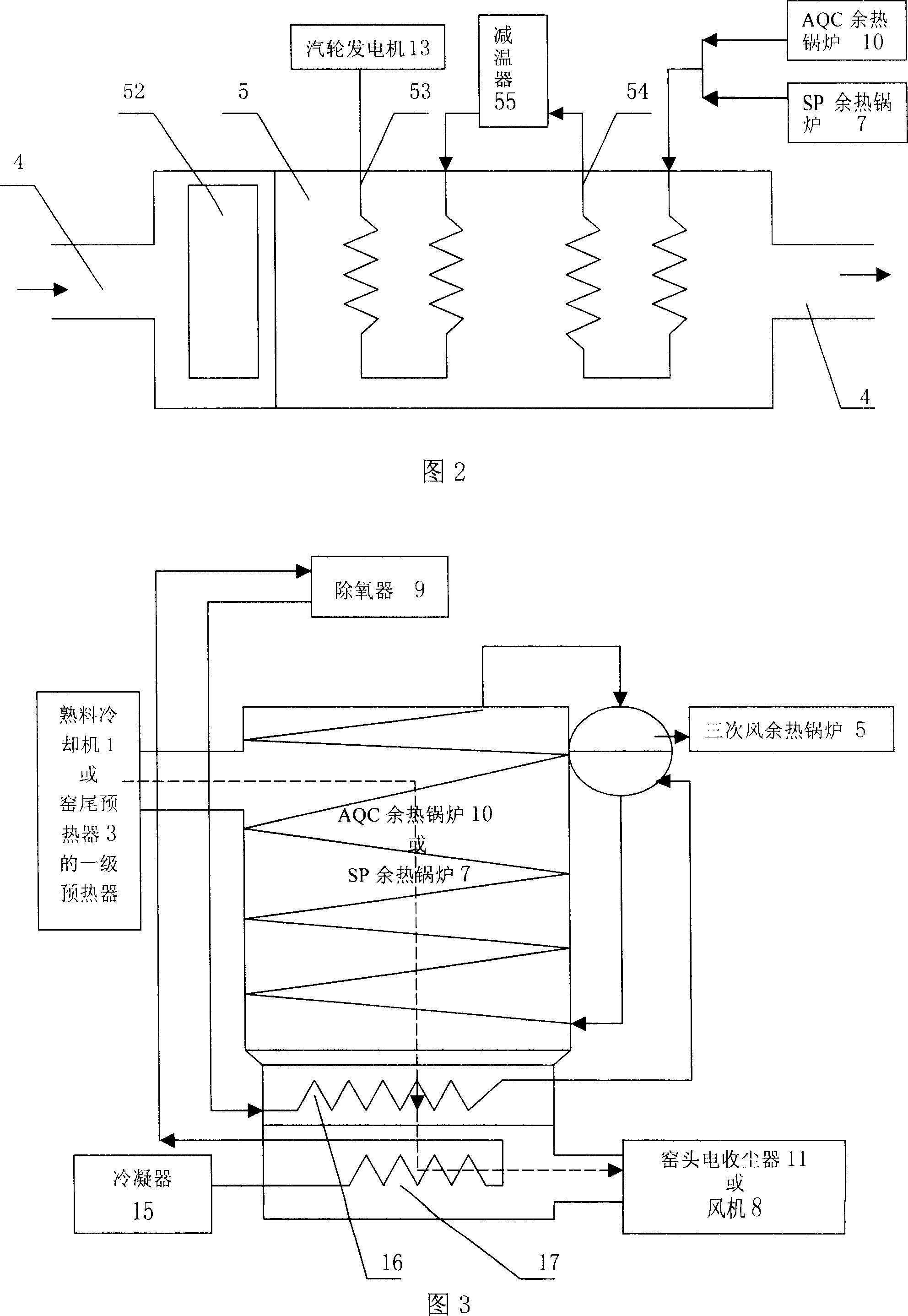
[0019] As shown in Figure 1 and Figure 3, the present invention consists of a clinker cooler 1, a cement rotary kiln 2, a cement preheater 3, a cement precalciner 3', a tertiary air duct 4, a tertiary air waste heat boiler 5, a bypass Air duct 6, SP waste heat boiler 7, induced draft fan 8, deaerator 9, AQC waste heat boiler 10, kiln head electric dust collector 11, induced draft fan 12, steam turbine 13, generator 14, condenser 15, cement rotary kiln Head shield 19 forms.

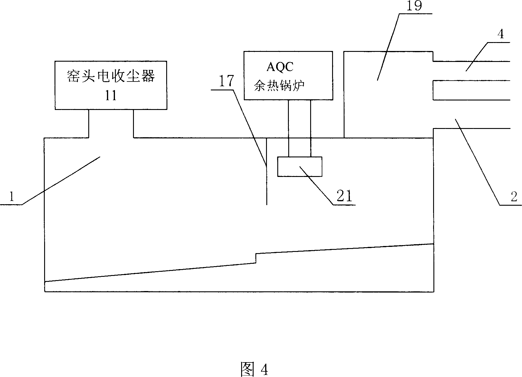
[0020] Among them, the discharge end of the cement rotary kiln 2 is connected to the feed end of the clinker cooler 1 through the cement rotary kiln kiln hood 19, the feed end is connected to the cement precalciner 3', and the AQC waste heat boiler 10 is connected to the clinker cooler. 1 The air extraction port 21 opened on the side wall is connected; the waste heat pipe of the SP waste heat boiler 7 is connected with the final stage outlet of the cement preheater 3; the working medium outlet of the AQC w...


PUM


Abstract

The invention discloses an abundant generating system used in dry cement product line, comprising a grog cooler, a AQC abundant heat boiler, a cement rotary furnace, a head frame of cement rotary furnace, a third-stage wind tube, a cement preheating device, a cement predissociation furnace, a SP abundant heat boiler, a fan, a deaerator, a condenser, and a generator of turbine. The third-stage wind tube is between the head frame and the predissociation furnace. The head frame is communicated with the grog cooler. The invention is characterized in that third-stage wind tube is arranged with a third-stage wind abundant-heat boiler with bypass wind channels; the medium inlet of the third-stage wind abundant-heat boiler via the tube is connected with the AQC abundant-heat boiler and the SP abundant-heat boiler, while the medium outlet is connected with the turbine generator. The invention can completely absorb the abundant heat of product line, to supply overheated steam to the generator, while the electricity generation is higher than 40kwh.

Description

technical field [0001] The invention relates to a waste heat power generation system for a new dry-process cement production line, which belongs to the field of cement production waste gas treatment and waste heat comprehensive utilization. Background technique [0002] At present, the pure low-temperature waste heat power generation system of the new dry-process cement production line commonly used at home and abroad is to use the hot air drawn from the cooling air outlet of the grate cooler at the kiln head of the existing cement production line and the flue gas discharged from the first-stage preheater. The heat is converted into the internal energy of water vapor through the waste heat boiler, and the steam-water circulation system of the 1950s is used to drive the turbine generator to generate electricity; The exhausted high-temperature flue gas has not been classified and utilized, and there are still problems such as air leakage, uneven air distribution, dust accumula...

Claims


Application Information

Patent Timeline
IPC IPC(8): F27D17/00
CPCY02P10/25Y02P40/121
Inventor 赵向东朱国桢张高佐王贵生关生林
Owner BEIJING LIULIHE CEMENT
Learn More