Automobile emergent brake and antiskid device
An emergency braking and anti-skid device technology, applied in the direction of brakes, brake components, vehicle parts, etc., can solve the problems of acceleration performance, braking efficiency reduction, anti-skid and complex structure of emergency braking devices, etc., to ensure braking performance , Improve the effect of adhesion friction
- Summary
- Abstract
- Description
- Claims
- Application Information
AI Technical Summary
Problems solved by technology
Method used
Image
Examples
Embodiment 1
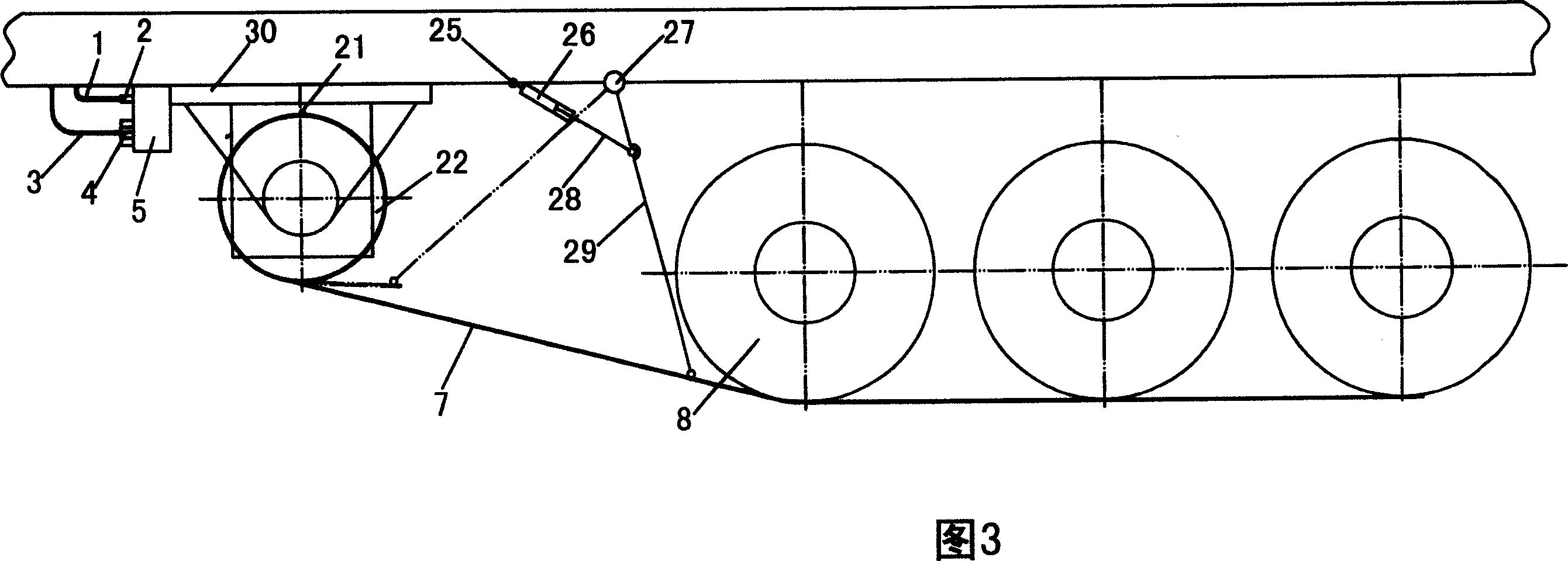
[0042] Please refer to Fig. 3, the length of each group of anti-skid belts 7 stretches out from the rear wheel 8 and exceeds the center line of the last wheel during work. When the driver sent the signal of emergency braking, the anti-skid belt 7 was sent to the front of the wheel accurately by the device, and was rolled over successively from the rear wheel 8 to the last wheel.
[0043] Working principle of embodiment one:
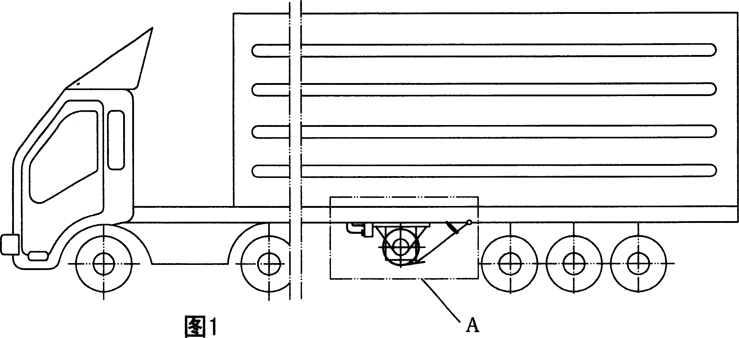
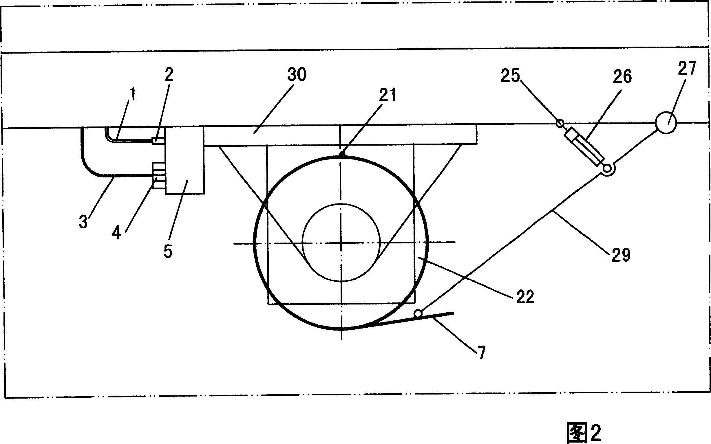
[0044] When the road is icy and snowy or the common braking system of the vehicle has a problem, the driver sends an emergency braking signal, and the assembly hinge 25, quick responder 26, hinge 27, push rod 28, and swing rod 29 form the sending device and assembly. The release device composed of 21 and 22 starts to work under the action of the control device composed of component 1, oil pipe 1, oil pipe joint 2, control harness 3, control harness joint 4, and controller 5. Push down, reach the position shown in Fig. 1 instantaneously, the front end of ...
Embodiment 2
[0046] Please refer to Fig. 4 and Fig. 10, the ferromagnetic object at the head end of each group of anti-skid belts 7 is firmly attracted to the electromagnet on the pick-up wheel 23 and wound on a pick-up wheel 23, which is connected to the drive motor 15 Connected, the pick-up wheel is pivotally connected to a slider 10, the slider is installed in the guide sleeve 12 and hinged to the piston rod 11 with the pin 9, the piston rod 11 is connected to the piston cylinder 13 installed in the guide sleeve 12, the guide The cover 12 is fixedly connected to the base 24 mounted on the chassis of the vehicle body.
[0047] Working principle of embodiment two:
[0048] For the convenience and safety of driving, on the basis of Example 1, an anti-skid belt pick-up device composed of components 9, 10, 11, 12, 13, 23, 24 is added, which can quickly pack up the anti-skid belt.
Embodiment 3
[0050] Please refer to Fig. 5, described each group of anti-slip belts 7 returns to release wheel 22 after being guided by pick-up wheel 23 and tug wheel device 6. See Figure 6.
[0051] Working principle of embodiment three:
[0052] When the vehicle is used in some special environments, in order to prevent the wheels from sliding on the ground for a long distance, the supporting roller 24 will be added on the basis of the second embodiment, so that the anti-skid belt 7 can be recycled.
[0053] During implementation, the structure of the anti-slip belt 7 is a grid-shaped high-strength flexible cable-net skeleton 17 outsourcing wear-resistant grid rubber 16, and a ferromagnetic object 18 mounted on the front end, as shown in Fig. 7 and Fig. 8 .
[0054] The structure of the anti-skid belt 7 can also be iron chains, tank crawlers and the like.
PUM
 Abstract
Description
Claims
Application Information
 - R&D
- Intellectual Property
- Life Sciences
- Materials
- Tech Scout
- Unparalleled Data Quality
- Higher Quality Content
- 60% Fewer Hallucinations
Browse by: Latest US Patents, China's latest patents, Technical Efficacy Thesaurus, Application Domain, Technology Topic, Popular Technical Reports.
© 2025 PatSnap. All rights reserved.Legal|Privacy policy|Modern Slavery Act Transparency Statement|Sitemap|About US| Contact US: help@patsnap.com


