Eureka AIR delivers breakthrough ideas for toughest innovation challenges, trusted by R&D personnel around the world.

Double cooled ozone discharging tube

A discharge tube and ozone technology, applied in the field of discharge tubes, can solve the problems affecting the efficiency of the ozone generator, unable to set up a high-power system, unable to effectively conduct heat, etc., to achieve a simple structure, improved odor yield, and low unit power consumption. Effect

Inactive Publication Date: 2007-07-25
TSINGHUA TONGFANG CO LTD
View PDF2 Cites 16 Cited by
  • Summary
  • Abstract
  • Description
  • Claims
  • Application Information

AI Technical Summary

Problems solved by technology

In the actual ozone generator, the outer metal tube of the low-voltage electrode of the ozone discharge tube is in circulating cooling water, which has relatively good heat dissipation conditions; while the working gas in the air gap in a laminar flow state cannot effectively conduct heat, so it lacks effective heat dissipation conditions The high-voltage electrodes are surrounded by high-temperature discharge air gaps, and in order to prevent corrosion, the discharge electrodes are all made of stainless steel with poorer thermal conductivity than carbon steel. This inefficient heat dissipation structure affects the further improvement of the efficiency of the ozone generator
Although in some technical solutions, the solution of dual cooling of inner and outer tubes is adopted, but the structure is complicated and it is impossible to build a high-power system, such as the technical solution disclosed in Chinese patent No. 99247355.1
Either the addition of a metal mesh structure between the inner and outer tubes not only weakens the heat dissipation effect, but also makes cleaning difficult, which greatly limits its application range

Method used


Image

  • Double cooled ozone discharging tube
  • Double cooled ozone discharging tube
  • Double cooled ozone discharging tube

Examples


Embodiment Construction

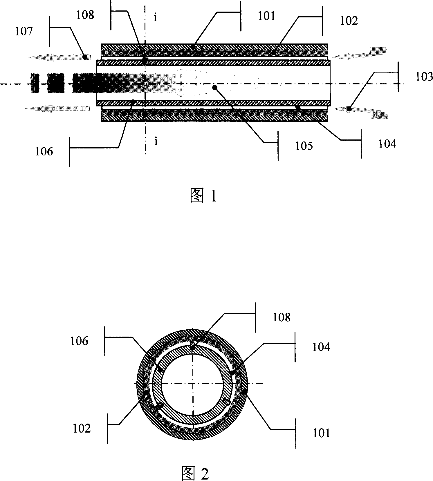
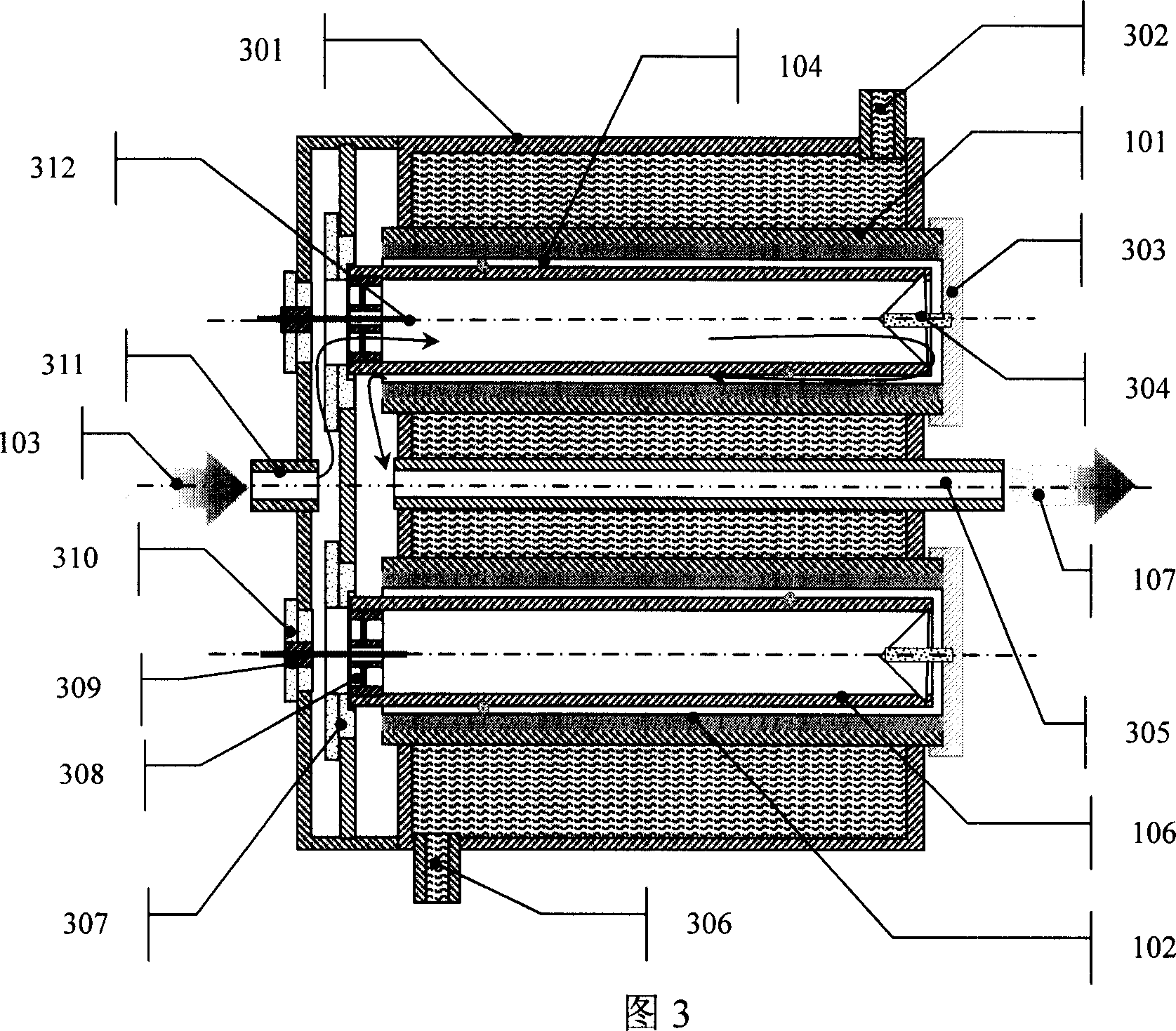
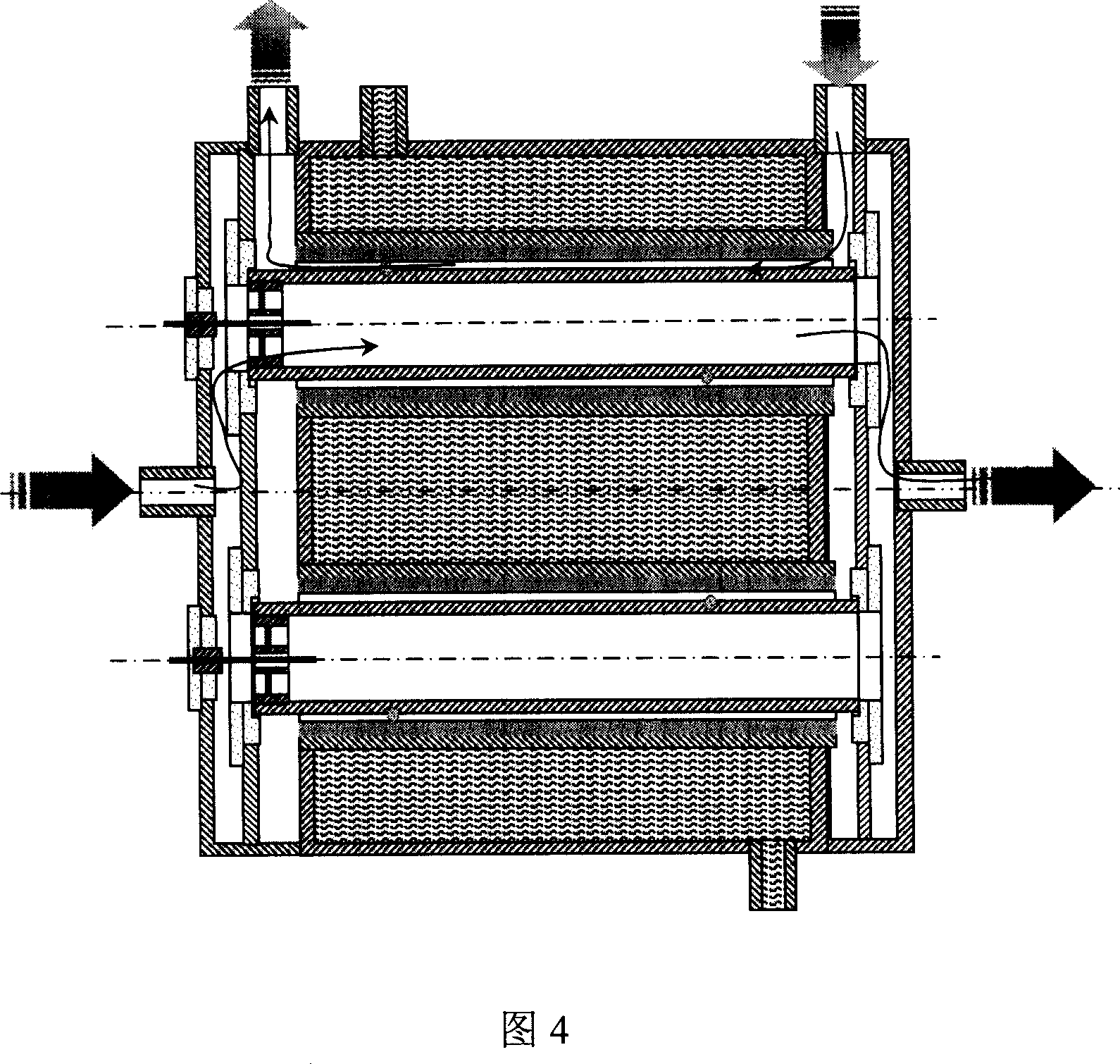
[0020] Referring to Fig. 1 and Fig. 2, the present invention includes a high-voltage electrode 106 and a ground electrode 101 made of metal tubes, and the surfaces of the high-voltage electrode 106 and the ground electrode 101 are plated with titanium or titanium alloy. The inner wall of the ground electrode 101 is lined with a dielectric layer 102 . The outer wall of the high-voltage electrode 106 is provided with a gap bump 108 supported by the dielectric layer 102 to form a sliding concentric circle, and an electric tube assembly with a discharge working air gap 104 . The thickness of the medium layer 102 is 0.3-1.5mm, and its material is one of ceramics, enamel, glaze, glass or a composite medium of several kinds. During use, the cooling gas 105 dissipates heat through the inner wall of the high-voltage electrode 106, the source gas 103 passes through the discharge working air gap 104 to form an ozone gas 107, and the ground electrode 101 is cooled by cooling water.

[00...


PUM

PropertyMeasurementUnit
thicknessaaaaaaaaaa

Abstract

This invention discloses a double-cooling ozone discharge tube for producing ozone. The discharge tube comprises a high-voltage electrode made of metal tube, and a ground electrode. A titanium layer is coated on the high-voltage electrode and the ground electrode. A dielectric layer is used as the inner lining of the ground electrode. A discharge tube assembly is placed at the outer wall of the high-voltage electrode, which forms a sliding concentric circle with the gap convex block supported by the dielectric layer, and has a discharge chamber air gap. The material for the dielectric layer is ceramic, enamel, glaze, glass, or their composite. Compared with the present technique, the discharge tube in this invention has such advantages as simple structure, high ozone generation efficiency, rapid assembly / disassembly, and easy cleaning. The discharge tube can be integrated into large power ozone generator.

Description

technical field [0001] The invention relates to a discharge tube for generating ozone, in particular to a double-cooled ozone discharge tube with a dielectric layer. Background technique [0002] At present, the structure of the known ozone discharge tube is composed of the outer metal tube as the ground electrode, the inner metal tube as the high voltage electrode, the dielectric layer attached to the outer wall of the inner metal tube, and the discharge gap between the dielectric layer and the ground electrode of the outer metal tube. Made, such as the representative Chinese patent 01268920.3, the products of the French OZONE company, etc. When the source gas such as air or oxygen passes through the discharge air gap between the high and low voltage electrodes loaded with AC voltage, it is ionized to form ozone. The contradiction between the ozone generated by the ionization of the source gas and the heat generated by the air gap discharge on the decomposition of ozone is...

Claims


Application Information

Patent Timeline
Patent Type & Authority Applications(China)
IPC IPC(8): C01B13/11
Inventor 罗璐朱翠萍杨高峰
Owner TSINGHUA TONGFANG CO LTD
Why Eureka
Eureka Blog
Learn More