System and method for measuring phase

A phase, low coherence technique applied in the field of systems and methods for phase measurement

Active Publication Date: 2010-02-17
MASSACHUSETTS INST OF TECH
View PDF8 Cites 2 Cited by
  • Summary
  • Abstract
  • Description
  • Claims
  • Application Information

AI Technical Summary

Problems solved by technology

However, little work has been done using nanoscale interferometry on weakly reflective samples such as biological cells and tissues

Method used


Image

  • System and method for measuring phase
  • System and method for measuring phase
  • System and method for measuring phase

Examples


Embodiment 1

[0436] Example 1: Phase imaging of calibration samples

[0437] In this example, calibrated samples were studied and illustrated that the present invention can provide quantitative information at the nanometer (nm) scale. The samples consisted of metal deposits on a glass substrate, which were then etched. The metal deposit pattern is in the shape of a figure "8" and the thickness of the metal layer is about 140nm as measured by a microscopic light wave interferometer.

[0438] Figures 60A-60D Shown are images acquired with the system using reflection geometry at four different phase shifts δ. Figure 60A is the image 2000 with δ=0; Figure 60B is the image 2200 of δ=π; Figure 60C is the image 2400 of δ=π / 2; and Figure 60D is an image 2600 of δ=3π / 2.

[0439] Figure 61 Schematically illustrates the electric field vector E 2102 and the high frequency wave vector component E of the electric field H and the low frequency wave vector component E of this electric fiel...

Embodiment 2

[0443] Example 2: Phase Imaging of Phase Grating

[0444] Figure 64 A phase image 2400 of a phase grating with trenches nominally 10 microns wide and nominally 266 nm deep obtained using transmission geometry is shown. exist Figure 64 Among them, the unit of Z axis 2402 is nm, and the unit of Y axis 2404 and X axis 2406 is CCD pixel. Vertical scale 2408 is also in nm and is provided to further aid in determining depth (Z-axis dimension) from phase image 2400 .

Embodiment 3

[0445] Example 3: Phase image of onion cells

[0446] In this example, onion cells were phase imaged using transmission geometry in accordance with the present invention. Intensity images of onion cells 2500 are shown at Figure 65 in order to be in Figure 66 Phase image 2550 shown in . exist Figure 65 and Figure 66 , the y-axis 2502, 2552 and the x-axis 2504, 2554 are in units of CCD pixels. Figure 66 The scale bar in 2556 is in nm.

[0447] Intensity image ( Figure 65 ) represents the first frame taken without a phase shift δ=0 between the low frequency component and the high frequency component. as compared Figure 65 and Figure 66 As shown, the conventional microscope (intensity) images have very low contrast relative to the phase images obtained according to the present invention. as in Figure 66 As seen in , the contrast in the phase image is greatly enhanced, and in this case much finer cellular structures can be distinguished. In addition, the info...


PUM

PropertyMeasurementUnit
lengthaaaaaaaaaa
thicknessaaaaaaaaaa
thicknessaaaaaaaaaa

Abstract

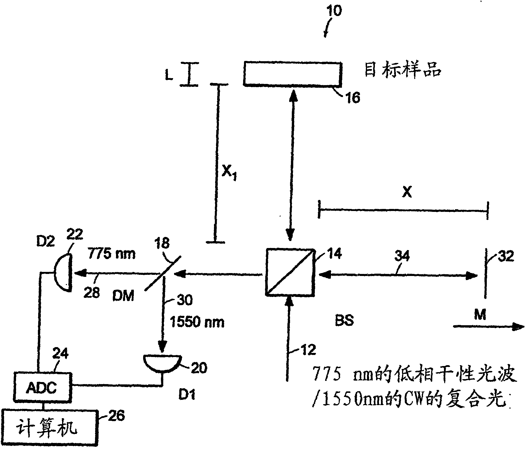
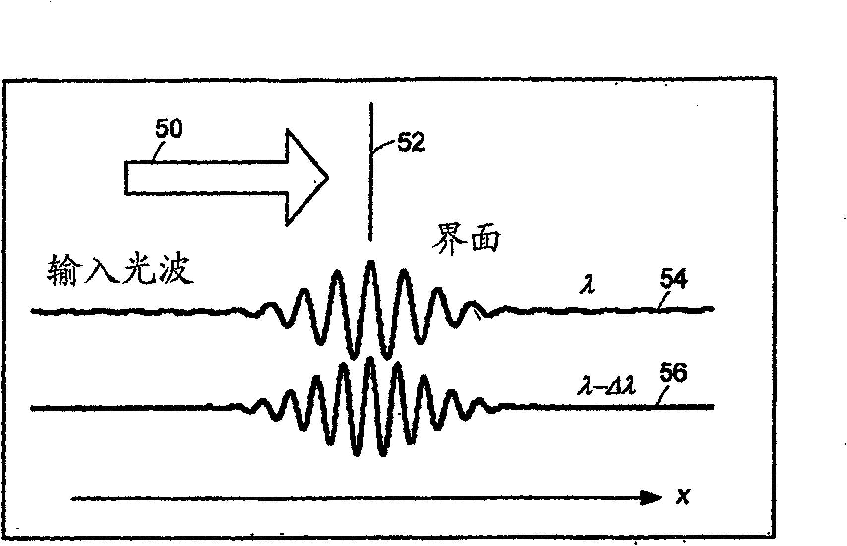
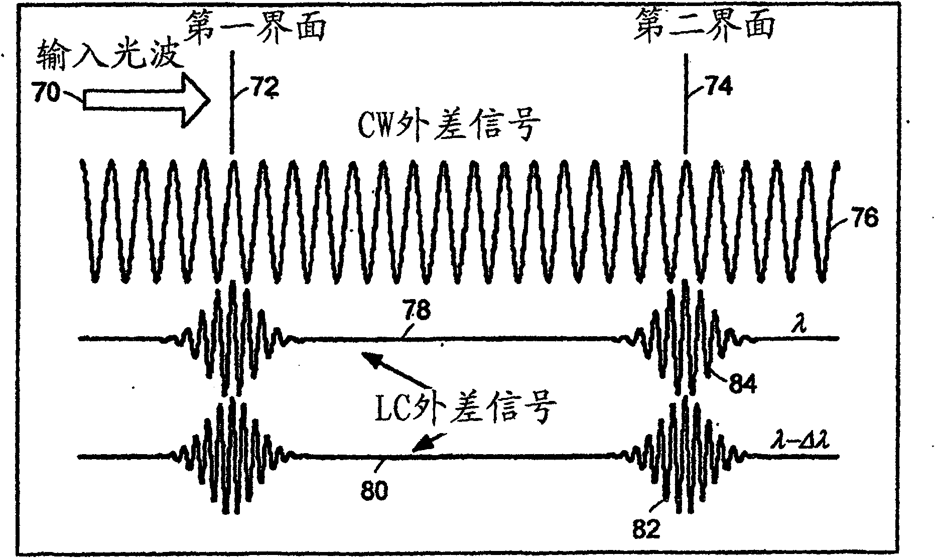
Preferred embodiments of the present invention are directed to systems for phase measurement which address the problem of phase noise using combinations of a number of strategies including, but not limited to, common-path interferometry, phase referencing, active stabilization and differential measurement. Embodiment are directed to optical devices for imaging small biological objects with light.These embodiments can be applied to the fields of, for example, cellular physiology and neuroscience. These preferred embodiments are based on principles of phase measurements and imaging technologies. The scientific motivation for using phase measurements and imaging technologies is derived from, for example, cellular biology at the sub-micron level which can include, without limitation, imagingorigins of dysplasia, cellular communication, neuronal transmission and implementation of the genetic code. The structure and dynamics of sub-cellular constituents cannot be currently studied in theirnative state using the existing methods and technologies including, for example, x-ray and neutron scattering. In contrast, light based techniques with nanometer resolution enable the cellular machinery to be studied in its native state. Thus, preferred embodiments of the present invention include systems based on principles of interferometry and / or phase measurements and are used to study cellular physiology. These systems include principles of low coherence interferometry (LCI) using optical interferometers to measure phase, or light scattering spectroscopy (LSS) wherein interference withinthe cellular components themselves is used, or in the alternative the principles of LCI and LSS can be combined to result in systems of the present invention.

Description

technical field [0001] This application is a successor-in-part of U.S. Patent Application No. 10 / 823,389 (filed April 13, 2004), which is a successor-in-part of U.S. Patent Application No. 10 / 024,455 (filed December 2001 18), and claims the benefit of US Patent Provisional Application No. 60 / 479,732 (filed June 19, 2003). [0002] The entire content of the above application is hereby incorporated by reference in its entirety. Background technique [0003] Phase-based optical interferometry techniques have been widely used for optical distance measurements requiring subwavelength distance sensitivity. Optical distance is defined as the product of refractive index and length. However, most such techniques are limited by problems well known in the field to 2π ambiguity or integer ambiguity which can be defined as describing the difficulty in axially scanning interferograms moving away from each other. Low-coherence interferometry (LCI) based on the unmodified harmonic phase ...

Claims


Application Information

Patent Timeline
Patent Type & Authority Patents(China)
IPC IPC(8): G01N21/45
Inventor 克里斯托弗·M·方严加布里埃尔·波普斯克杨昌辉亚当·P·沃克斯拉曼查德·R·戴萨瑞迈克尔·S·费尔德
Owner MASSACHUSETTS INST OF TECH
Why Eureka
Try Eureka