Compressor and operation method

A method of operation and compressor technology, which is applied to mechanical equipment, machines/engines, rotary piston pumps, etc., can solve the problems of reduced filter function, excessive loss of mechanical parts, pollution, etc., and achieve the effect of avoiding backflow

Active Publication Date: 2010-01-27
코벨코컴프레서가부시키가이샤
View PDF4 Cites 0 Cited by
  • Summary
  • Abstract
  • Description
  • Claims
  • Application Information

AI Technical Summary

Problems solved by technology

The control using the suction control valve has the following problems: the suction control valve must be frequently opened and closed, the mechanical parts such as the valve body of the suction control valve are worn out a lot, and the pressure pulsation is easy to occur.
[0007] However, in an oil-cooled screw compressor, the gas leaked to the suction side moves with the oil, and when the speed drops to a very low speed, the amount of gas leaked to the suction side will be larger than the amount of gas pushed out to the discharge side. As the amount of gas increases, the oil flows back to the suction side, and the suction filter installed in the flow path on the suction side becomes contaminated with oil, resulting in a decrease in the function of the filter and a reduction in the suction volume.

Method used


Image

  • Compressor and operation method
  • Compressor and operation method
  • Compressor and operation method

Examples


Embodiment Construction

[0019] Embodiments of the present invention will be described below with reference to the drawings.

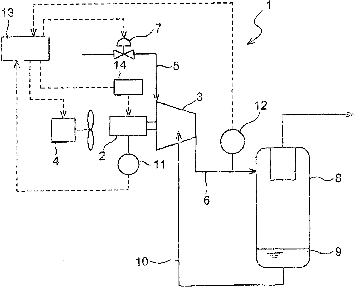
[0020] figure 1 An oil-cooled screw compressor 1 according to an embodiment of the present invention is shown. The oil-cooled screw compressor 1 has a compressor main body 3 in which a pair of male and female screw rotors driven by a motor 2 and engaged with each other are accommodated. In the vicinity of the motor 2 of the compressor body 3 , a cooling fan 4 is provided so as to blow air toward the motor 2 . A suction flow path 5 is connected to one side of the compressor main body 3 , and a discharge flow path 6 is connected to the other side. An on-off valve 7 is provided in the suction flow path 5 . An oil separator 8 is provided in the discharge flow path 6 . Extending from the oil storage part 9 at the lower part of the oil separation and recovery device 8 is an oil flow path 10 communicating with the oil supply parts such as the rotor chamber, the bearing part and t...


PUM


Abstract

The invention provides a compressor and an operating method thereof. A switching valve is fixed at the suction side of the main body of the compressor, and lower limit rotation rate of the motor is setted in a control device, wherein the gas volume discharged to the discharging side of the main body of the compressor is approximately same with gas volume leaked to the suction side. When the rotation rate of the motor is in a range above the lower limit rotation rate and below the upper limit rotation rate, a control device determins a control rotation rate for eliminating the bias of the detected pressure relatively to the preestablished target pressure, opens the switching valve when the control rotation rate is bigger than the lower limit rotation rate, and closes the switching valve when the control rotation rate is smaller than the lower limit rotation rate. According to the constructure, the range of the rotation rate control relatively to the volume control can be expanded, and the reflux of the oil to the suction side can be avoided.

Description

technical field [0001] The present invention relates to a compressor and a method of operating the same. Background technique [0002] In general, in a screw compressor, the rotation of the screw rotors pushes out gas on the discharge side, but the gas leaks to the suction side due to gaps formed between the screw rotors or between the screw rotors and the casing. As the rotational speed decreases, the leakage of the gas to the suction side becomes more obvious. [0003] In order to avoid an increase in the leakage of compressed gas to the low-pressure side of the compressor body due to an excessive reduction in the rotational speed of the motor driving the main body of the oil-free screw compressor, for example, the following method is described in JP-A-2002-054578: When the speed is higher than the preset value, the suction regulating valve on the suction side of the compressor body is opened to control the motor speed, and when the speed reaches the preset value, the spe...

Claims


Application Information

Patent Timeline
Patent Type & Authority Patents(China)
IPC IPC(8): F04C18/16F04B49/06F04C28/00
Inventor 吉村省二中村元黑田建志
Owner 코벨코컴프레서가부시키가이샤
Why Eureka
Try Eureka