
Dispensing apparatus for dispensing liquid crystal

A dispenser, liquid crystal technology, applied in liquid distribution, distribution devices, special distribution devices, etc., can solve problems such as uneven distribution of liquid crystals and changes in liquid crystal temperature

Inactive Publication Date: 2009-12-23
金 东贤
View PDF6 Cites 0 Cited by
  • Summary
  • Abstract
  • Description
  • Claims
  • Application Information

AI Technical Summary

Problems solved by technology

This results in dispensing of uneven amounts of liquid crystals based on changes in liquid crystal viscosity
[0011] Changes in liquid crystal temperature may occur due to changes in ambient temperature or high heat generated by repeated opening and closing operations of the valve

Method used


Image

  • Dispensing apparatus for dispensing liquid crystal
  • Dispensing apparatus for dispensing liquid crystal
  • Dispensing apparatus for dispensing liquid crystal

Examples


Embodiment Construction

[0022] Reference will now be made in detail to the preferred embodiments of the invention, examples of which are illustrated in the accompanying drawings.

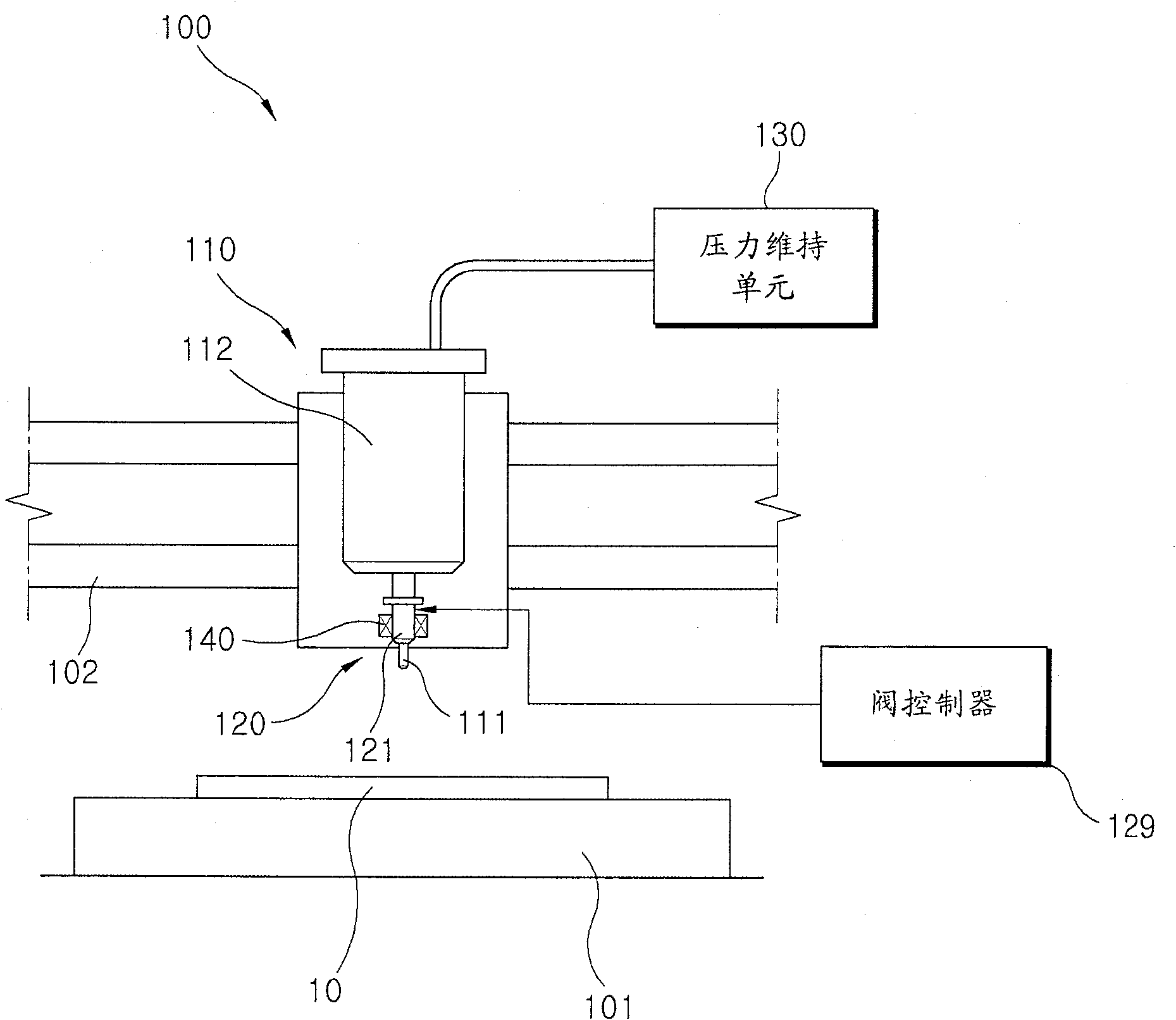
[0023] figure 1 is a view showing the structure of a dispenser for dispensing liquid according to an embodiment of the present invention.

[0024] refer to figure 1 , the dispenser 100 for dispensing liquid according to an embodiment of the present invention includes a nozzle 111 through which liquid such as liquid crystal is dispensed.

[0025] The liquid contained in the syringe 112 is dispensed on the substrate 10 through the nozzle 111 which moves relative to the substrate 10 . The nozzle 111 is provided on the dispensing head unit 110 supported by the head support frame 102 which is movably provided on the main body 101 in one direction. The dispensing head unit 110 is provided to be movable in a direction opposite to the direction in which the head support frame 102 is movable. This makes the nozzle 111 movable r...


PUM


Abstract

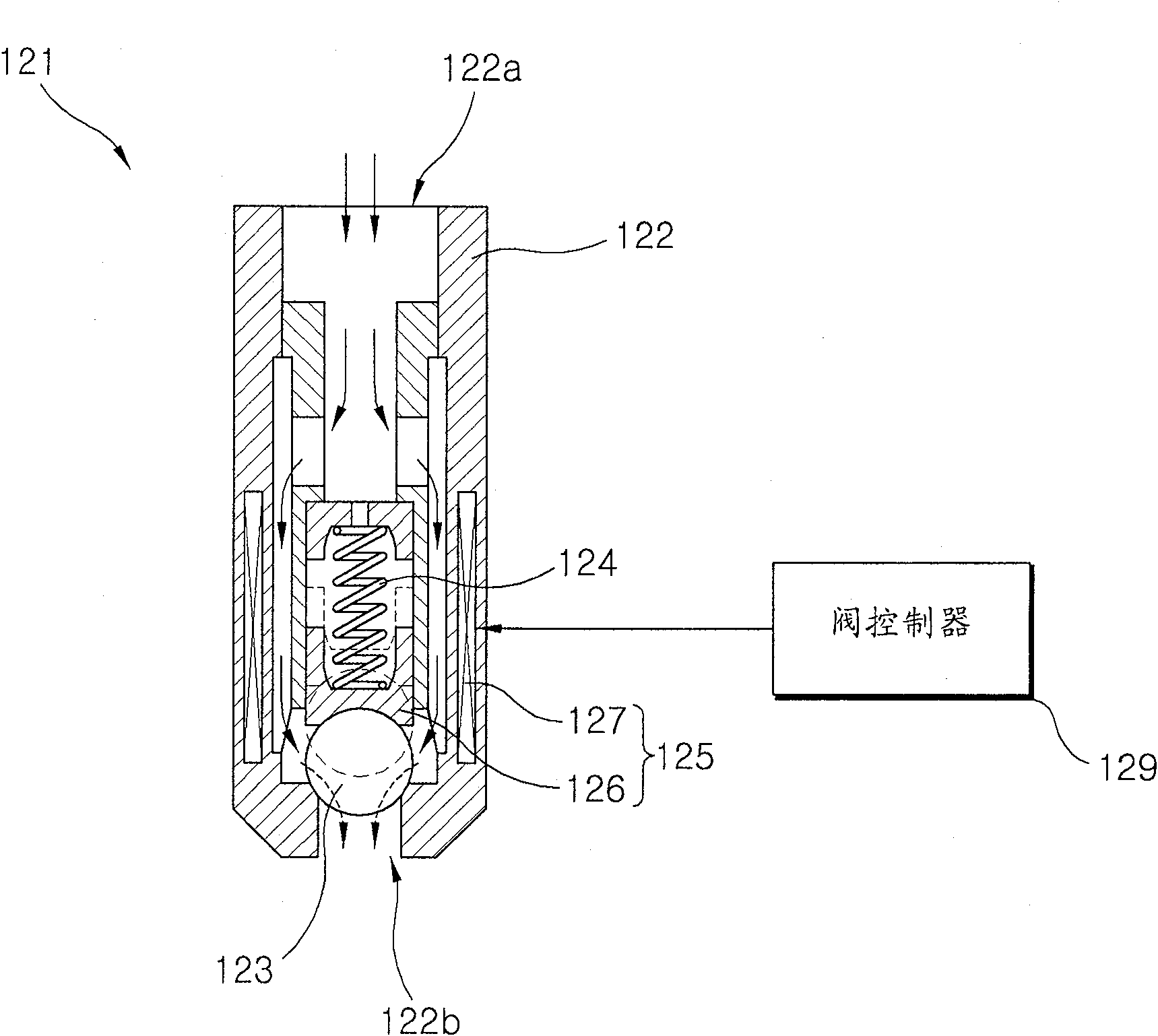
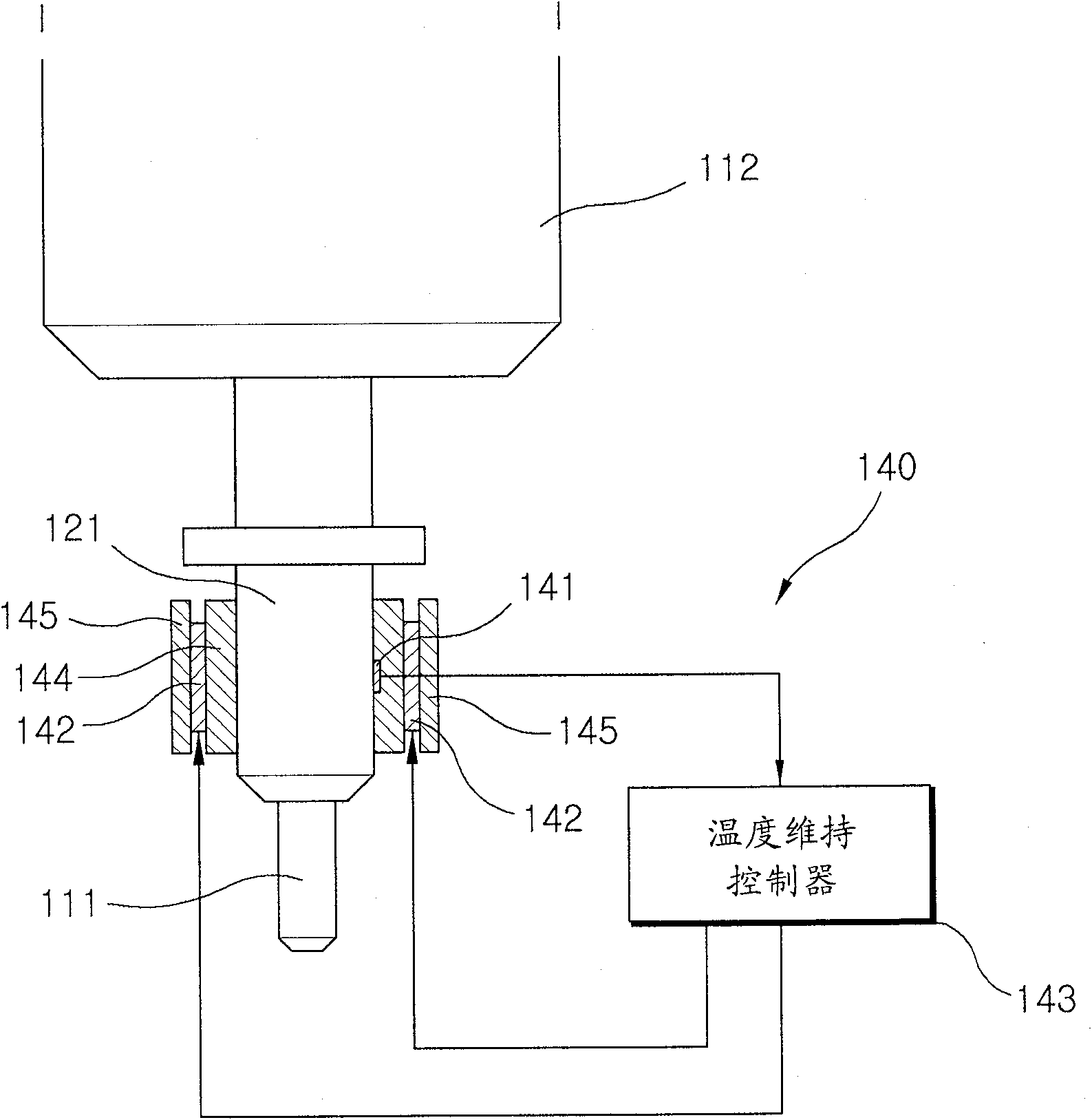
The present invention provides a dispenser for dispensing a liquid on a substrate, the dispenser comprising: a nozzle through which a liquid contained in a syringe is dispensed on the substrate, the nozzle moving relative to the substrate; a valve unit with Used to control the distribution of liquid through the nozzle, and a temperature maintaining unit to maintain the temperature of the liquid passing through the valve at a preset temperature, wherein the valve unit includes: a valve that is opened and closed to control the flow from the syringe to the nozzle liquid flow; and a valve controller for controlling the opening and closing operation of the valve. The present invention offers the advantage of dispensing a metered amount of liquid without the effect of temperature changes on the viscosity of the liquid.

Description

[0001] Related Application Cross Reference [0002] This application claims the benefit and priority of Korean Patent Application No. 2006-105054 filed on October 27, 2006, the entire contents of which are hereby incorporated by reference. technical field [0003] The present invention relates to a dispenser for dispensing liquid, and more particularly, to a dispenser for dispensing metered amounts of liquid on glass substrates used in the manufacture of liquid crystal panels. Background technique [0004] Flat panel displays comprise a growing technology that enables video displays to be lighter and much thinner than conventional televisions and video displays using cathode ray tubes, typically less than 10 cm (4 feet) thick. Flat panel displays that need to be continuously updated include liquid crystal displays (LCDs), plasma displays, field emission displays (FEDs), organic light emitting diode displays (OLEDs), surface conduction electron emission displays (SEDs), nano-...

Claims


Application Information

Patent Timeline
Patent Type & Authority Patents(China)
IPC IPC(8): G02F1/1339G02F1/1333F16K1/14F16K31/06B67D7/80B67D7/36B67D7/58B67D99/00
CPCB05C5/001G02F2001/13415G02F1/1341B05C5/0225G02F1/1303G02F1/13415B67D7/36B67D7/58B67D99/00
Inventor 孙世豪陈明填
Owner 金 东贤
Learn More