
Magnetic bearing motor and its magnetic bearing assembly

A technology of magnetic bearings and components, applied in the direction of bearing components, bearings, bearing unloading, etc., can solve the problems that magnetic bearings cannot enter the mass production stage smoothly, the auxiliary magnet adsorption angle is incorrect, and cannot run smoothly, etc., to achieve low friction , avoid manufacturing, improve the effect of operating life

Inactive Publication Date: 2009-12-16
DELTA ELECTRONICS INC
View PDF19 Cites 0 Cited by
  • Summary
  • Abstract
  • Description
  • Claims
  • Application Information

AI Technical Summary

Problems solved by technology

However, due to the incorrect force arm and adsorption angle of the auxiliary magnet, the auxiliary magnet will be attracted together during operation and cannot operate smoothly.
[0010] Therefore, when the magnetic levitation motor mentioned in the above-mentioned patent is running, the shaft center is likely to collide with the bearing, which increases its noise, shortens its life, and even prevents it from running smoothly.
And because of its magnetic balance, problems such as inability to start smoothly occur.
Therefore, the magnetic bearing is still in the experimental stage and cannot smoothly enter the mass production stage (practical stage)

Method used


Image

  • Magnetic bearing motor and its magnetic bearing assembly
  • Magnetic bearing motor and its magnetic bearing assembly
  • Magnetic bearing motor and its magnetic bearing assembly

Examples


Embodiment Construction

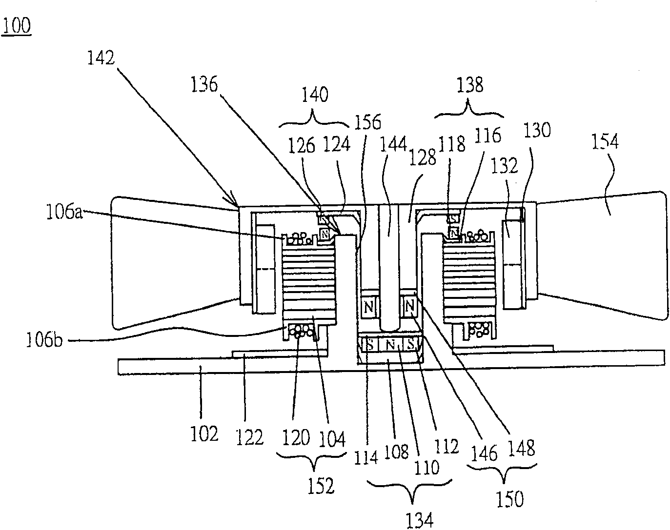
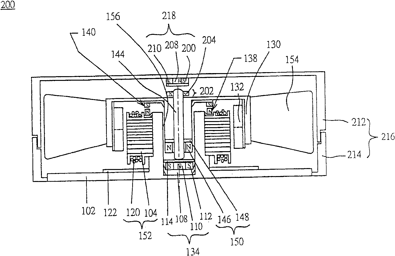
[0036] figure 1is a schematic diagram illustrating the magnetic bearing motor 100 according to the first preferred embodiment of the present invention. Please refer to figure 1 , the magnetic bearing motor 100 is composed of a rotating assembly 142 and a stator assembly 136, wherein in a static state, there is only a single point of contact between the rotating assembly 142 and the stator assembly 136, and in a running state, the contact between the rotating assembly 142 and the stator assembly 136 There is only a single point of contact or no contact between them.

[0037] The stator assembly 136 is composed of the stator base 102 , the stator poles 152 , and the magnetic positioning assemblies 134 , 138 . The stator base 102 is a convex component or a cylindrical component with an opening 156 at the center for carrying the rotating component 142 . The material of the stator base 102 is, for example, plastic, nonmagnetic rigid material, metal, or alloy.

[0038] The stato...


PUM


Abstract

A motor comprising a stator (136), a rotor (142), and a plurality of blades (154). The stator comprises a stator base (102) with an opening, a first magnetic structure (134) disposed at a bottom of the opening, a magnetic pole disposed on the stator base, and a second magnetic structure (138) disposed at a top of the magnetic pole. The rotor, coupled to the stator, comprises a hub (128), a shaft (144), a third magnetic structure (150) disposed at the hub and encircled one en of the shaft and corresponded to the first magnetic structure, and a fourth magnetic structure (140) disposed at the hub without contacting the second magnetic structure. The blades encircle the rotor. The first and third magnetic structures attract the second and the fourth magnetic structures, respectively.

Description

technical field [0001] The present invention relates to a magnetic-bearing motor, fan and bearing assembly thereof, in particular to a magnetic-bearing motor, fan and bearing assembly having the characteristics of low wear, low noise, low cost, and long life . Background technique [0002] In today's motors, in order to make it run smoothly, the shaft center of the rotor is usually covered by a bearing, so that the rotor can run smoothly with the support of the bearing. [0003] The existing bearings are Palin bearings, oil bearings (sleeve bearings), dynamic pressure bearings, ceramic bearings, etc. However, each of the aforementioned bearings has its own advantages and disadvantages. [0004] Palin bearings are also called ball bearings. The structure of this type of bearing is quite fragile, so it cannot withstand the impact of external force, and it will generate a lot of noise at high speed. Furthermore, due to the high precision requirement of the components, the pri...

Claims


Application Information

Patent Timeline
Patent Type & Authority Patents(China)
IPC IPC(8): F04D29/04H02K1/06F04D25/06F04D29/058F16C39/06H02K7/09
CPCF16C32/0417F04D29/058F16C39/063H02K7/09F04D25/062F16C2360/46
Inventor 陈李龙黄建雄黄世民黄文喜
Owner DELTA ELECTRONICS INC
Learn More