
Low NOx DC micro-oil coal powder burner

A pulverized coal burner and burner technology, applied in the direction of burners, burners burning powder fuel, combustion methods, etc., can solve the problems of low NOx combustion characteristics, human health hazards, environmental pollution, etc., to reduce emissions, turbulence The effect of enhancing the effect and saving ignition oil

Inactive Publication Date: 2009-12-02
HANGZHOU E ENERGY ELECTRIC POWER TECH
View PDF6 Cites 0 Cited by
  • Summary
  • Abstract
  • Description
  • Claims
  • Application Information

AI Technical Summary

Problems solved by technology

[0002] In the pulverized coal boiler, the thick-lean combustion technology is often used, that is, the pulverized coal flow into the furnace is inertially separated, divided into two streams of thick and thin, and then sent to the furnace respectively. It has been significantly improved, and its ignition characteristics have been significantly improved. However, when the pulverized coal is burned in the burner, it will produce atmospheric pollutants NOx, which will cause serious harm to environmental pollution and human health, especially for poor-quality combustion. For difficult-to-combust fuels such as bituminous coal and lean coal, it is more difficult to meet the requirements of low NOx emissions
For this reason, a low NOx pulverized coal burner came into being, such as a horizontal rich-lean burner, which adopts a sawtooth multi-strand nozzle structure at the outlet of the dense pulverized coal. This burner shows good combustion stability and low load Running performance, and has low NOx combustion characteristics, but it will reduce the above effects when burning non-combustible fuels, and still cannot effectively reduce NOx emissions

Method used


Image

  • Low NOx DC micro-oil coal powder burner
  • Low NOx DC micro-oil coal powder burner
  • Low NOx DC micro-oil coal powder burner

Examples


Embodiment Construction

[0014] Below in conjunction with embodiment and accompanying drawing, the present invention will be further described:

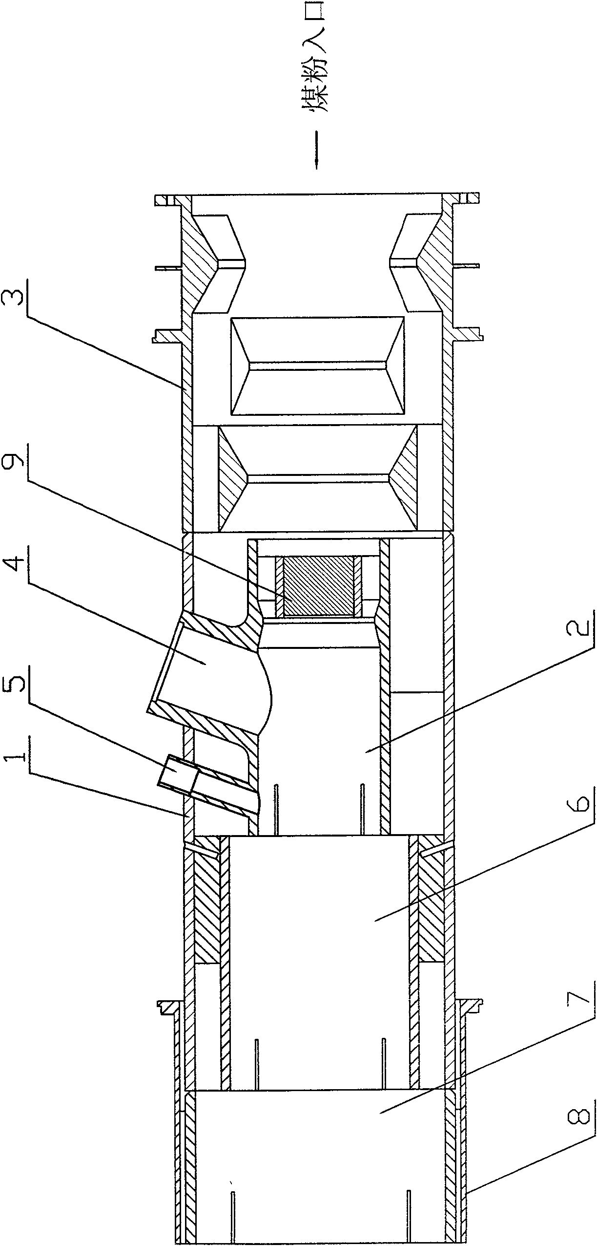
[0015] see figure 1 , the present invention includes a burner body 1 and a primary combustion chamber 2 placed in the burner body 1, an annular pulverized coal concentrator 3 is provided at the entrance of the burner body 1, and an oil combustion chamber 4 is obliquely inserted from the burner body 1 In the primary combustion chamber 2, in order to observe the situation in the combustion chamber, an observation port 5 is obliquely inserted into the primary combustion chamber 2 from the burner body 1. According to actual needs, a secondary combustion chamber 6 and a tertiary combustion chamber 7 can also be set. , The outlet of the burner body 1 is provided with a film air inlet 8, and a cooling air with a relatively low temperature enters from the air film air inlet 8 to cool the wall of the burner, thereby prolonging the service life of the burner.

[0016...


PUM


Abstract

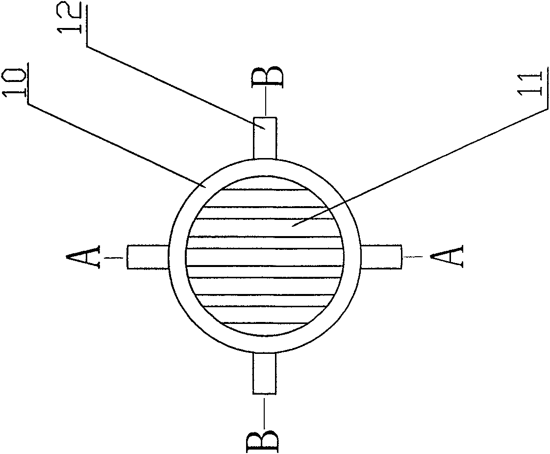
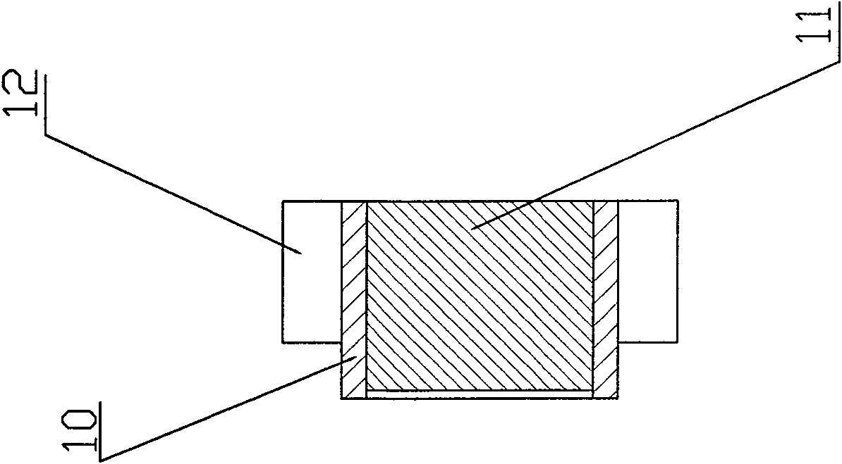
The invention relates to a low-NOx direct current micro-oil pulverized coal burner. The burner comprises a burner body and a primary burning chamber arranged inside the burner body; an inlet of the burner body is provided with a pulverized coal concentrator; an oil burning chamber is obliquely inserted into the primary burning chamber from the burner body; the burner is characterized in that: an inlet of the primary burning chamber is provided with a grid-type airflow regulator. The grid-type airflow regulator is provided with a round tube; the round tube is alternately provided with a plurality of clapboards. The low-NOx direct current micro-oil pulverized coal burner has the following advantages that: as the grid-type airflow regulator is arranged, After the condensed pulverized coal passes through the grid-type airflow regulator, the pulverized coal is further thickened; at the same time, onflow effect is reinforced; micro-oil flame ejected from the oil burning chamber firstly ignites the pulverized coal in the burning chamber; as the onflow effect is strong and the pulverized coal in the burning chamber has high concentration, the burning chamber is in a reducing atmosphere during burning process and mass NOx generated from burning is deacidized, thereby reducing the emission of pollutants.

Description

technical field [0001] The invention belongs to a pulverized coal burner, in particular to a low NOx direct-flow micro-oil pulverized coal burner. Background technique [0002] In the pulverized coal boiler, the thick-lean combustion technology is often used, that is, the pulverized coal flow into the furnace is inertially separated, divided into two streams of thick and thin, and then sent to the furnace respectively. It has been significantly improved, and its ignition characteristics have been significantly improved. However, when the pulverized coal is burned in the burner, it will produce atmospheric pollutants NOx, which will cause serious harm to environmental pollution and human health, especially for poor-quality combustion. For difficult-to-combust fuels such as bituminous coal and lean coal, it is more difficult to meet the requirements of low NOx emissions. For this reason, a low NOx pulverized coal burner came into being, such as a horizontal rich-lean burner, ...

Claims


Application Information

Patent Timeline
Patent Type & Authority Patents(China)
IPC IPC(8): F23D1/02
Inventor 李凤瑞
Owner HANGZHOU E ENERGY ELECTRIC POWER TECH
Learn More