Distribution photometer with tracing reflectors

A technology of goniophotometer and mirror, which is applied in the direction of spectrometry/spectrophotometry/monochromator, optical radiation measurement, measuring device, etc. It can solve the problems affecting measurement accuracy, beam dead angle, fixed mirror surface shape error, etc. problem, achieve the effects of reducing stray light, high measurement accuracy, and small footprint

Active Publication Date: 2009-11-25
HANGZHOU ZHEJIANG UNIV SENSING INSTR
View PDF6 Cites 0 Cited by
  • Summary
  • Abstract
  • Description
  • Claims
  • Application Information

AI Technical Summary

Problems solved by technology

The disadvantage of this structure is that the measuring light beam makes a relative conical change on the fixed reflector 4, and the inconsistency of the reflectance of the fixed reflector in each direction affects the measurement accuracy, and because the light detection device and the main reflector move together, it is difficult to move between the light detection device and the main reflector. A series of light barriers to eliminate stray light are set between the tested lamps, otherwise there will be a dead angle of the beam; the beam axis is incident on the fixed reflector from all directions on a conical surface, and then reflected to the moving light detection device, due to the fixed reflector The reflectance in all directions of space is not the same, which will introduce obvious photometric error; in addition, the surface shape error of the fixed reflector, the surrounding reflected stray light is sensitive to the influence of photometric measurement accuracy

Method used


Image

  • Distribution photometer with tracing reflectors
  • Distribution photometer with tracing reflectors
  • Distribution photometer with tracing reflectors

Examples


Embodiment Construction

[0034] The present invention will be further described below in conjunction with the accompanying drawings.

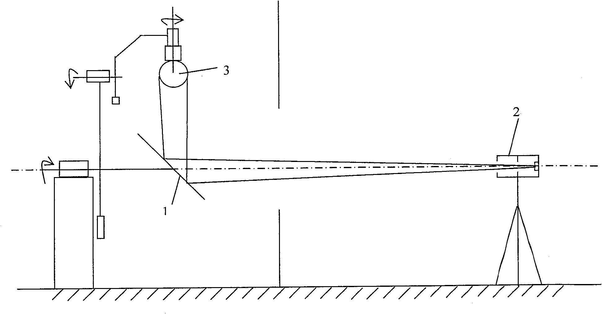
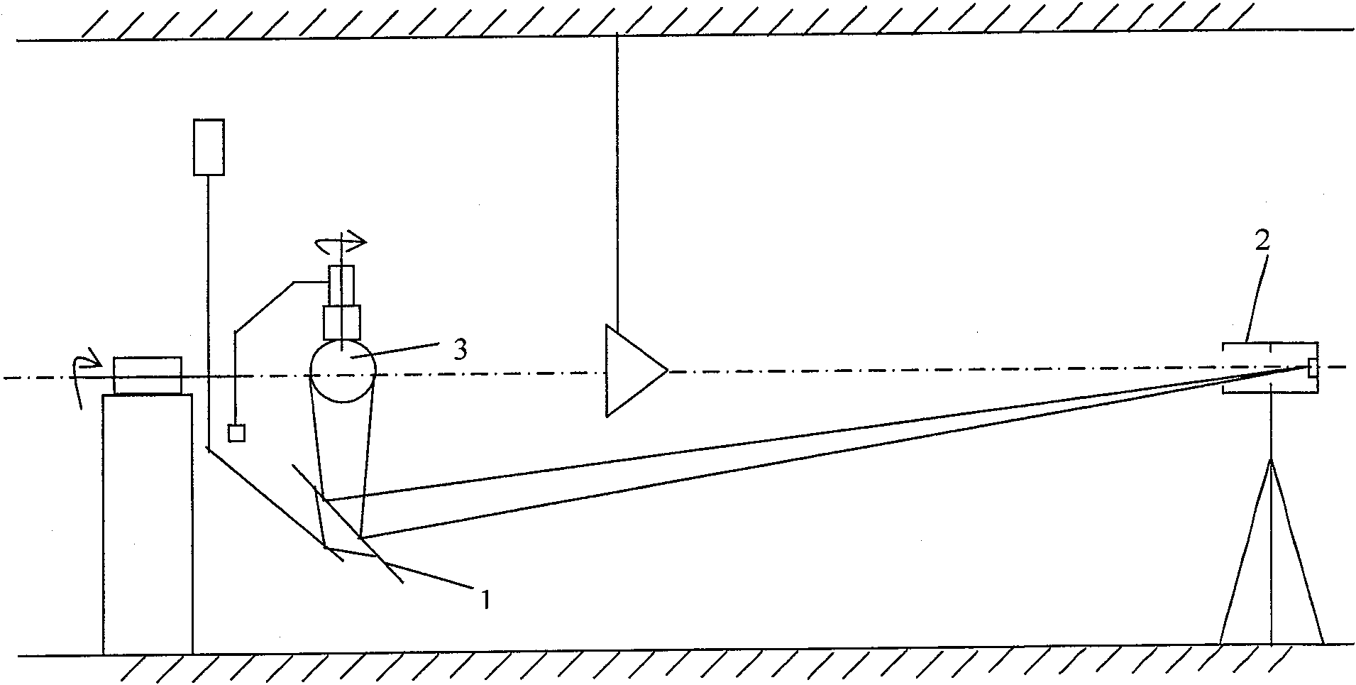
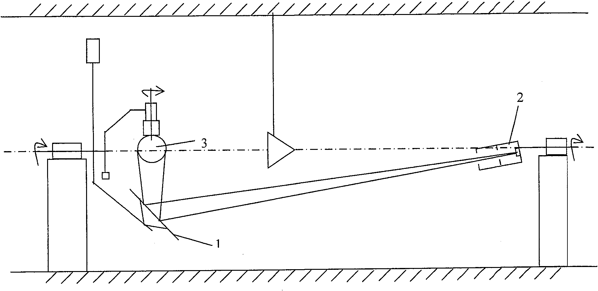
[0035] refer to Image 6 , the goniophotometer with tracking mirror includes a main mirror rotating table, a synchronous tracking rotating table, a lamp rotating table and a light detection device;

[0036] The main reflector rotating table includes: a main base 1-1, a main reflector frame 1-3 and a main reflector 1-4, a main rotating shaft 1-2 is installed on the main base 1-1, and a main reflector frame 1 -3 is fastened on the main rotating shaft 1-2, the rotation center of the main mirror frame 1-3 coincides with the axis of the main rotating shaft 1-2, and the main mirror 1-4 is fixed on the main mirror frame 1-3, The main rotating shaft 1-2 is driven to rotate by the main motor 1-5;

[0037] The synchronous tracking rotary table includes: a synchronous base 2-1 and a synchronous mirror 2-4 that receives reflected light from the main mirror 1-4. The synchronous t...


PUM


Abstract

The goniophotometer with tracking mirror of the present invention includes a main mirror rotating table, a synchronous tracking rotating table, a lamp rotating table and a light detection device; when working, the lamp to be tested is fixed on the rotating shaft of the lamp, and when the main rotating shaft rotates, it drives The main reflector rotates, and the rotation of the synchronous tracking rotation axis drives the synchronous reflector to rotate synchronously with the main reflector. The rotation axis of the lamp drives the luminaire under test to rotate. The light detection device receives and measures the light distribution of the lamp under test. The goniophotometer adopts a synchronous mirror that rotates synchronously with the main mirror. The reflected light path of the synchronous mirror coincides with the axis of the synchronous tracking rotation axis. The reflected light is vertically incident on the light detection device, which can eliminate the directional pair test of the synchronous mirror. The influence of the result, and it is easy to set the stray light elimination diaphragm on the optical channel, the measurement accuracy is high, and the space occupied is small.

Description

technical field [0001] The invention relates to a distribution photometer, especially a distribution photometer with a tracking mirror. Background technique [0002] Commonly used goniophotometers with mirrors are as follows: one is the center rotating mirror goniophotometer, such as figure 1 As shown, the light detection device 2 is fixed, and the main reflector 1 rotates, so that the tested lamp 3 rotates and rotates synchronously and reversely around the main reflector 1, and performs circular translation in space to realize the measurement of the light intensity of the tested lamp in different directions. Since the tested luminaire is moving during the test, the environment of the tested luminaire in different locations is different, and the ambient temperature and moving air flow will affect the measurement accuracy of the temperature-sensitive luminaire; [0003] The second type is a moving mirror goniophotometer. The main mirror 1 rotates around the tested lamp 3, an...

Claims


Application Information

Patent Timeline
Patent Type & Authority Patents(China)
IPC IPC(8): G01J3/00G01J3/02
Inventor 牟同升
Owner HANGZHOU ZHEJIANG UNIV SENSING INSTR
Why Eureka
Try Eureka