Zero-voltage switch full-bridge direct current converter

A technology of zero-voltage switching and DC converters, which is applied in the direction of converting DC power input to DC power output, adjusting electrical variables, and high-efficiency power electronic conversion. It can solve the problem of increasing the volume and cost of the converter, increasing the output filter capacitor, clamping The problem of bit diode damage is eliminated, and the effects of eliminating voltage oscillation, reducing current, and eliminating loss are achieved.

Inactive Publication Date: 2009-11-18
NANJING UNIV OF AERONAUTICS & ASTRONAUTICS
View PDF5 Cites 0 Cited by
  • Summary
  • Abstract
  • Description
  • Claims
  • Application Information

AI Technical Summary

Problems solved by technology

In order to meet the output voltage ripple requirements, the output filter capacitor needs to be increased, which increases the size and cost of the converter.
At the same time, when the converter works under light load or even no-load conditions, the duty cycle is relatively small, and the clamp diode is hard turned off, which is easy to cause damage to the clamp diode

Method used


Image

  • Zero-voltage switch full-bridge direct current converter
  • Zero-voltage switch full-bridge direct current converter
  • Zero-voltage switch full-bridge direct current converter

Examples


Embodiment Construction

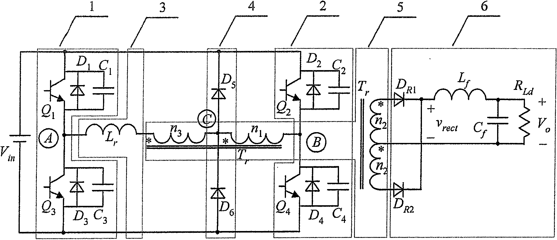
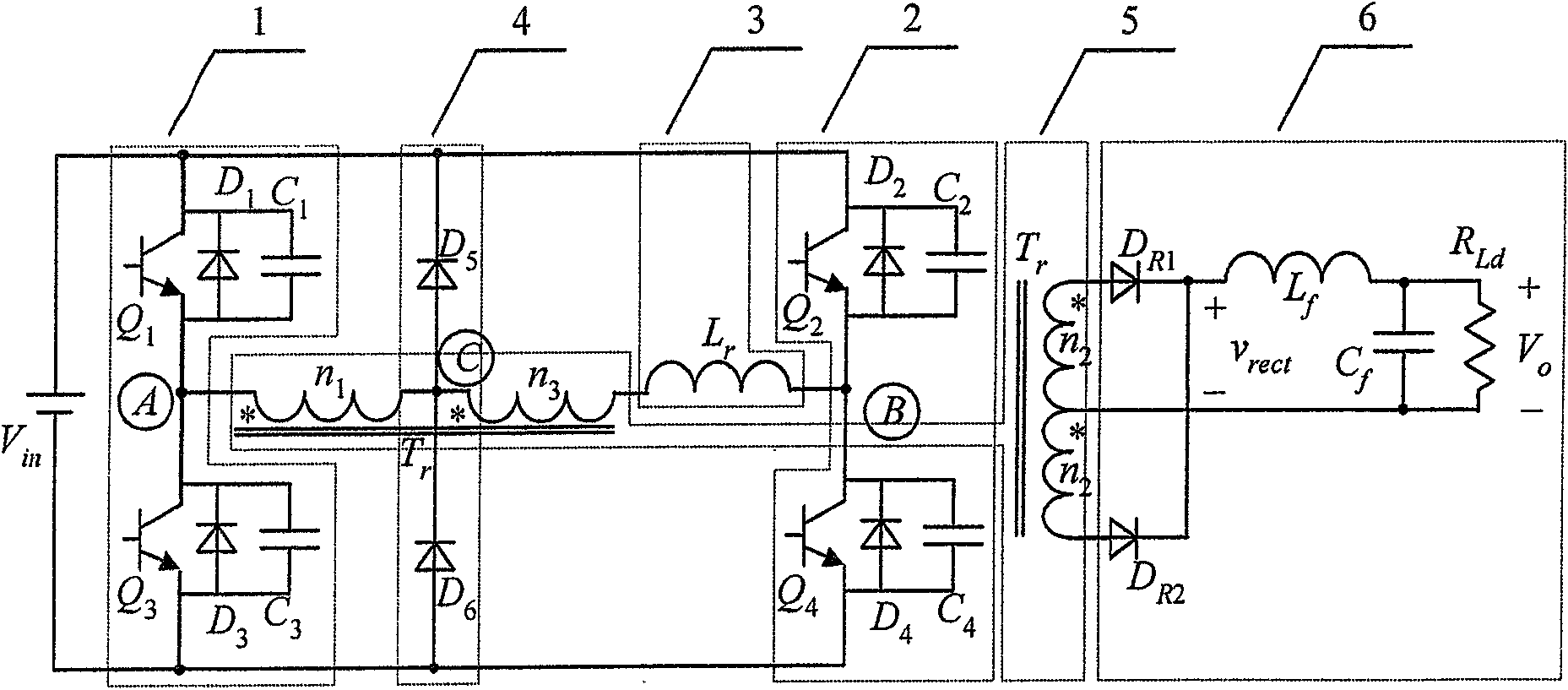
[0011] attached figure 1 And attached figure 2 Shown are two schematic diagrams of the circuit structure of the zero-voltage switching full-bridge DC converter with the auxiliary winding of the transformer. by the DC power supply V in , two inverter bridge arms 1 and 2, a resonant inductor 3, a clamp circuit 4, an isolation transformer 5, and a rectification and filter circuit 6. Q 1 ~Q 4 are four main switch tubes, D 1 ~D 4 are the switching tube Q 1 ~Q 4 body diode, C 1 ~C 4 respectively switch Q 1 ~Q 4 The parasitic capacitance, L r is the resonant inductance, T r is the isolation transformer, D R1 and D R2 is the output rectifier diode, L f is the output filter inductor, C f is the output filter capacitor, R Ld for the load. The converter adopts phase-shift control, the switch tube Q 1 and Q 3 Respectively ahead of the switching tube Q 4 and Q 2 One phase, called switch tube Q 1 and Q 3 The first inverter bridge arm formed is the leading bridge ar...


PUM


Abstract

This DC converter belongs to the energy converter and consists of the DC power supply (Vin), two inverter bridge arms, the resonance inductance, the isolation transformer and the rectifier / filter circuit. Its character lays on that; there is an auxiliary winding (n3) in the isolation transformer beside the primary and the secondary windings (n1, n2). One end of n3 is connected to n1 and to two clamp diodes from the joint point to form a clamping circuit. Another end of n3 is connected to the resonance inductance. This converter realizes the zero voltage switching on the rectifier. This can eliminate the voltage oscillation induced by the reverse restoration of the output rectifier. It decrease the voltage stress across the output rectifier and reduces rapidly and effectively the currents through the clamping diodes. All these raise the conversion efficiency and improve the work condition of clamping diodes during light load.

Description

1. Technical field [0001] The zero-voltage switching full-bridge DC converter of the invention belongs to the DC converter of an electric energy conversion device. 2. Background technology [0002] In medium and high power DC conversion occasions, the full bridge converter has been widely used because the switching tube is easy to realize soft switching and adopts constant frequency control. In the past two decades, there have been many soft-switching control strategies and circuit topologies for full-bridge converters. Both the phase-shift control zero-voltage switching full-bridge converter and the phase-shift control zero-voltage zero-current switching full-bridge converter can realize the soft switching of the switching tube. However, whether it is a zero-voltage switching or zero-voltage zero-current switching full-bridge converter, due to the reverse recovery of the secondary rectifier diode, the leakage inductance of the transformer (or the additional resonant induct...

Claims


Application Information

Patent Timeline
Patent Type & Authority Patents(China)
IPC IPC(8): H02M3/28H02M3/335H02M7/5387
CPCY02B70/1491Y02B70/10
Inventor 阮新波陈武
Owner NANJING UNIV OF AERONAUTICS & ASTRONAUTICS
Why Eureka
Try Eureka