
Moving-cover type electric pressure cooker

A moving cover type, electric technology, applied in the direction of pressure cooker, etc., can solve the problems of limited elastic displacement parameters of elastic elements, high cost of outer pot materials, increased process difficulty and complexity, etc., to ensure effectiveness, save material costs, simplify The effect of craft

Inactive Publication Date: 2009-11-18
王永光
View PDF11 Cites 64 Cited by
  • Summary
  • Abstract
  • Description
  • Claims
  • Application Information

AI Technical Summary

Problems solved by technology

There are some problems in the implementation of the above-mentioned existing patented technology, mainly in the integrated design of the product. It is difficult to integrate the design of the elastic element and the design of the outer pot, even if the two are reluctantly integrated. The bottom of the pot is designed to be elastic. Although the elastic bottom of the pot can realize the function of the elastic element, because the elastic element and the outer pot have different requirements on the materials, although the area of ​​the material participating in the elastic deformation is only a small part of the bottom of the outer pot. In order to meet the requirements of the elastic element on the elastic strength (that is, the elastic force), it is necessary to use a stainless steel plate with better elasticity to make the entire outer pot. , so that the elastic displacement parameter of the elastic element is also limited
And if the elastic element is not integrated with other parts, it is independently arranged in a certain part of the outer pot, although the cost of the outer pot can be slightly reduced, but due to the mechanical connection between the elastic element and other related parts, it is necessary to carry The pressure in the pot increases the difficulty and complexity of the process during production and processing, making the yield unsatisfactory

Method used


Image

  • Moving-cover type electric pressure cooker
  • Moving-cover type electric pressure cooker
  • Moving-cover type electric pressure cooker

Examples


Embodiment

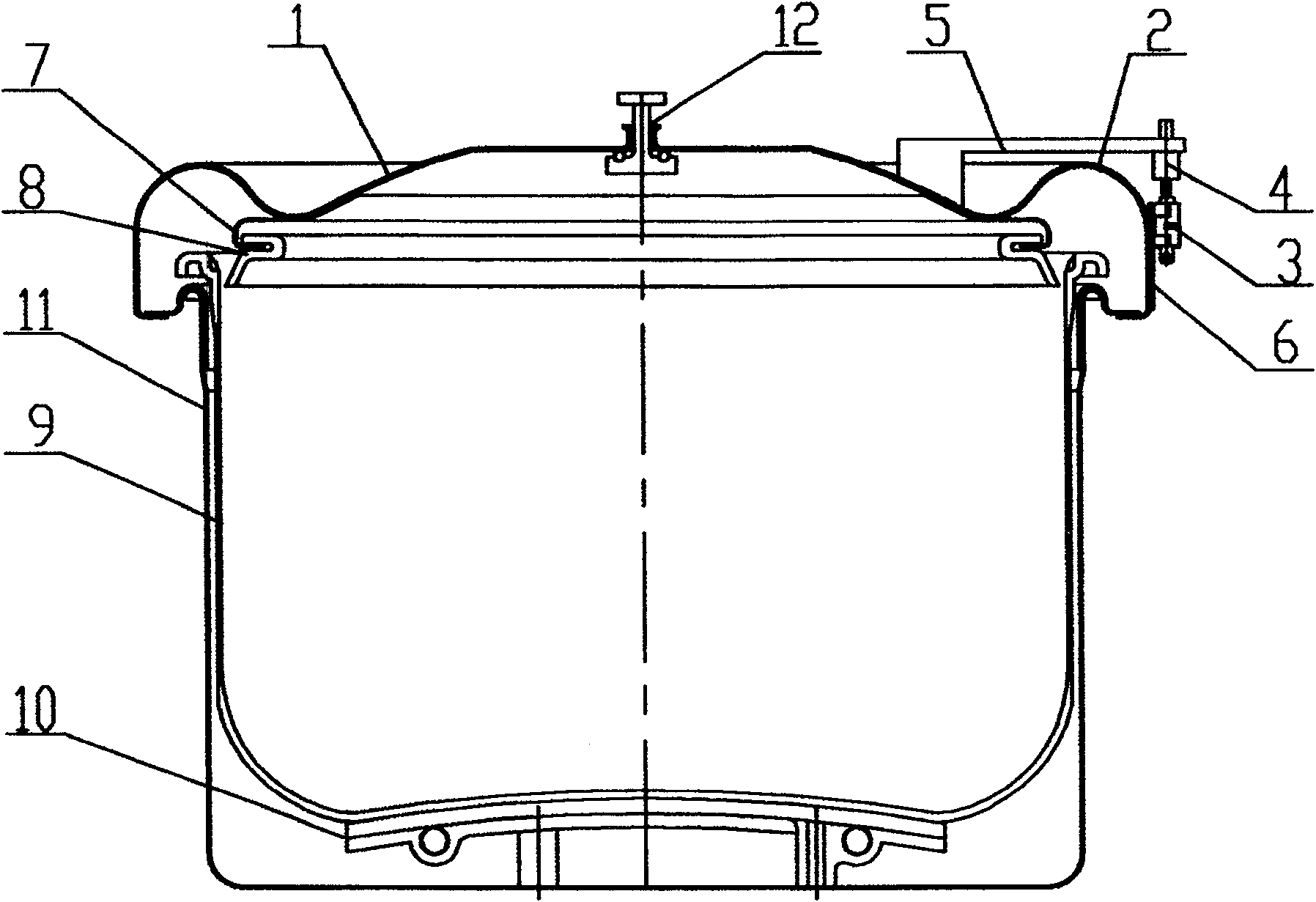
[0029] Embodiment: Take the caliber 20cm of the inner pot 9 as an example. Adopt the aluminum plate of thickness 2.5mm, inner pot 9 is stretched and formed, on the inner side of its pot edge, the top of sealing ring 8 sealing positions, along the circumference evenly arrange some pressure relief grooves (as 8). The size of each pressure relief groove is: the radial direction of the inner pot 9 is about 4mm, the arc in the circumferential direction is about 5°, and the height dimension (the dimension extending downward from the pot along the plane) is also the height dimension of the pressure relief ring line. It is directly related to the limit value of the maximum pressure in the pot, and should be designed in conjunction with the height of the sealing ring 8, the height of the sealing part of the pot cover 1, and the displacement of the elastic element 2 to obtain the required pressure relief value. The sealing ring 8 is made of high-quality silicon rubber, and its sealing d...


PUM


Abstract

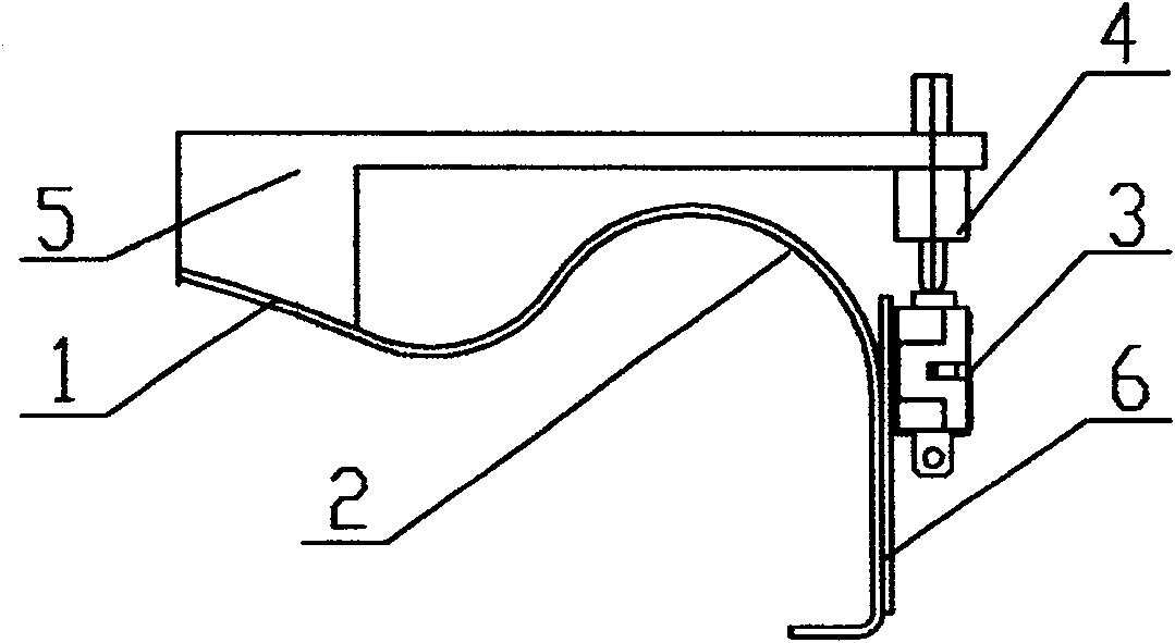
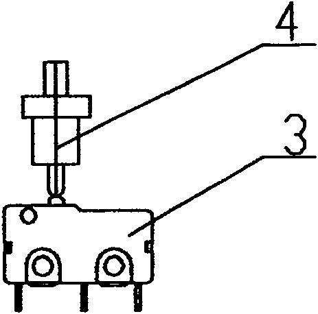
The invention relates to a movable cover electric pressure cooker, which belongs to kitchen electric appliances, and is a patented technology of electric rice cooker pressurization that controls and limits the pressure inside the cooker through an elastic cooker cover. It includes a pot cover, an elastic element, a switch, a sealing ring, an inner pot, an electric heater, and an outer pot; the edge of the inner pot sits on the edge of the outer pot; The outer pot is movable and rigidly connected; the elastic element controls the on-off of the switch by the elastic displacement generated under the pressure in the pot, and the elastic displacement is transmitted to the corresponding device through the transmission part arranged at the displacement or static position of the elastic element. on the switch. The invention can solve the problems in the integrated design and mechanical connection of the elastic element and other parts in the prior art, improve the utilization rate of materials, simplify the production process and reduce the production cost.

Description

Technical field: [0001] The invention belongs to kitchen appliances, and is a patented technology of electric rice cooker pressurization that controls and limits the pressure in the pot through the elastic displacement of the pot cover. Background technique: [0002] Existing electric rice cooker pressure products (hereinafter referred to as electric pressure cooker) or patented technology, the pressure control scheme mostly adopts the elastic element arranged on a certain part of the outer pot, and the elastic element is used to produce pressure under the action of the inner pressure of the pot. The method of controlling the switch on and off by elastic displacement realizes the closed-loop automatic control of the pressure inside the pot, such as: Chinese invention patent ZL91100026.7 sets the elastic element at the bottom of the outer pot; ZL98100976.X sets the elastic element in the middle of the outer pot; In ZL97100738.1, the elastic element is arranged on the teeth of...

Claims


Application Information

Patent Timeline
Patent Type & Authority Patents(China)
IPC IPC(8): A47J27/08
Inventor 王永光
Owner 王永光
Learn More