
A magnetic shielding device with multi-layer compound structure for shielding strong magnetic field

A multi-layer composite and magnetic shielding technology, which is applied in shielding, magnetic field/electric field shielding, instrument parts, etc., can solve problems such as inability to shield strong magnetic fields

Inactive Publication Date: 2009-09-30
INST OF HIGH ENERGY PHYSICS CHINESE ACAD OF SCI
View PDF3 Cites 3 Cited by
  • Summary
  • Abstract
  • Description
  • Claims
  • Application Information

AI Technical Summary

Problems solved by technology

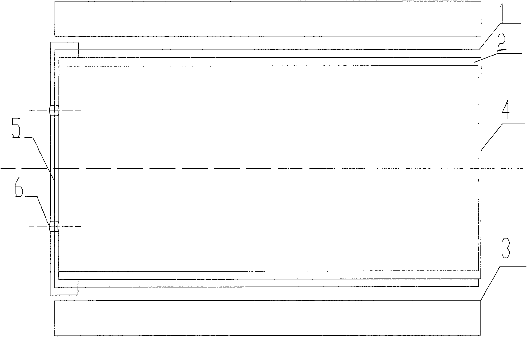
[0006] Aiming at the problem that the general magnetic shielding design of the current photomultiplier tube cannot shield the strong magnetic field, the purpose of the present invention is to provide a magnetic shield with a multi-layer composite structure that can make the photomultiplier tube work normally under the strong magnetic field and is used to shield the strong magnetic field. shielding device

Method used


Image

  • A magnetic shielding device with multi-layer compound structure for shielding strong magnetic field
  • A magnetic shielding device with multi-layer compound structure for shielding strong magnetic field
  • A magnetic shielding device with multi-layer compound structure for shielding strong magnetic field

Examples


Embodiment Construction

[0019] The utility model will be described in detail below in conjunction with the accompanying drawings. It should be noted that the described embodiments are only intended to facilitate the understanding of the present invention, and have no limiting effect on it.

[0020] like figure 1 As shown in the schematic diagram of the magnetic shielding device with a multilayer composite structure for shielding strong magnetic fields of the present invention, it includes a silicon steel part 1, an alloy part 2, a solenoid coil 3, a front end cover 4, a rear end cover 5, and a joint hole 6. It includes three layers, the outermost layer is a solenoid coil 3, the middle layer is a silicon steel part 1, and the innermost layer is an alloy part 2, wherein the silicon steel part 1 is made of silicon steel. The alloy part 2 is made of permalloy material; the solenoid wire 3 turns are made of copper core wire.

[0021] The solenoid coil 3, the silicon steel part 1, and the alloy part 2 ado...


PUM


Abstract

Being in use for shielding strong magnetic field (MF), the magnetic shielding device with multilaminar composite structure solves issue that the design of magnetic shielding photomultiplier is unable to shield strong MF. Using multilaminar composite structure, the magnetic shielding device includes three layers from outer to inner: silicon steel assembly as middle layer, alloy assembly as inner layer, and solenoidal inductor as outer layer. The solenoidal inductor generates MF opposite to outer MF so as to weaken strong MF greatly. With higher saturation of MF, the silicon steel assembly reduces outer MF to a few Gauss further. Possessing quite high magnetic permeability of weak MF, the alloy assembly in innermost layer reduces residual MF to lower than 0.001 Gauss being far lower than level of earth MF. The invention makes shielded photomultiplier operate normally under strong MF. The invention has wide application in technical areas of nuclear electronics and nuclear detection.

Description

technical field [0001] The invention relates to the technical field of nuclear electronics and nuclear detection, in particular to a magnetic shielding device for a photomultiplier tube used for shielding a strong magnetic field. Background technique [0002] The photomultiplier tube is a photodetection device based on the photoelectric effect and secondary electron emission, which can convert weak optical signals into measurable electrical signals. It has high detection sensitivity, fast time response, large magnification, and good linearity of photoelectric characteristics. , stable performance, easy to use and other advantages, are widely used in spectroscopy, nuclear physics, medicine and other fields. The photomultiplier tube is mainly composed of a photoemission cathode (photocathode), a focusing electrode, an electron multiplier (dynode) and an electron collector (anode), all of which are encapsulated in a vacuum. Incident light illuminates the photocathode, which em...

Claims


Application Information

Patent Timeline
Patent Type & Authority Patents(China)
IPC IPC(8): H05K9/00G12B17/02
Inventor 马雁云王平章志明秦秀波于润生王宝义魏龙
Owner INST OF HIGH ENERGY PHYSICS CHINESE ACAD OF SCI
Learn More