Dynamic injecting system of injection moulder, and its vibration injecting method

An injection molding machine and dynamic technology, applied in the field of polymer dynamic injection, can solve the problems that the screw rod cannot realize large thrust drive, cannot realize large thrust movement, and increase equipment investment, etc. low cost effect

Active Publication Date: 2009-09-30
佛山市顺德区震德塑料机械有限公司
View PDF4 Cites 0 Cited by
  • Summary
  • Abstract
  • Description
  • Claims
  • Application Information

AI Technical Summary

Problems solved by technology

[0002] In the existing injection molding machine, in order to realize the reciprocating linear motion of the injection screw, the following four types of injection mechanism structures are generally used: (1) Use the oil cylinder to directly drive the screw to reciprocate (see figure 1 ); this scheme has low cost and has been used for decades at home and abroad; but this technology uses hydraulic oil as the transmission medium, resulting in large energy consumption, oil pressure pollution, and slow response
(2) Use the ball screw to drive the screw, and use the motor to drive the screw nut to realize the reciprocating motion of the rolling screw (similar structure figure 2 ); compared with the first scheme, this scheme has fast response speed, relatively simple control, improved precision, and is more environmentally friendly; but due to the high cost of the screw, the maintenance cost is also high, and a single screw cannot achieve large Thrust drive, if you need to achieve a larger thrust, you must use multiple motors to drive multiple screw rods to move synchronously. Realizing the synchronous action of multiple motors and multiple screw rods is not only complicated to control, but also high in cost, so it cannot be fully promoted and used in the industry
(3) Use a linear motor to directly drive the screw for reciprocating motion; this scheme has a simple structure and quick response; but its cost is high, and it cannot achieve high-thrust motion (see image 3 )
This method increases the investment of equipment while introducing the vibration effect, and consumes energy itself.

Method used


Image

  • Dynamic injecting system of injection moulder, and its vibration injecting method
  • Dynamic injecting system of injection moulder, and its vibration injecting method
  • Dynamic injecting system of injection moulder, and its vibration injecting method

Examples


Embodiment

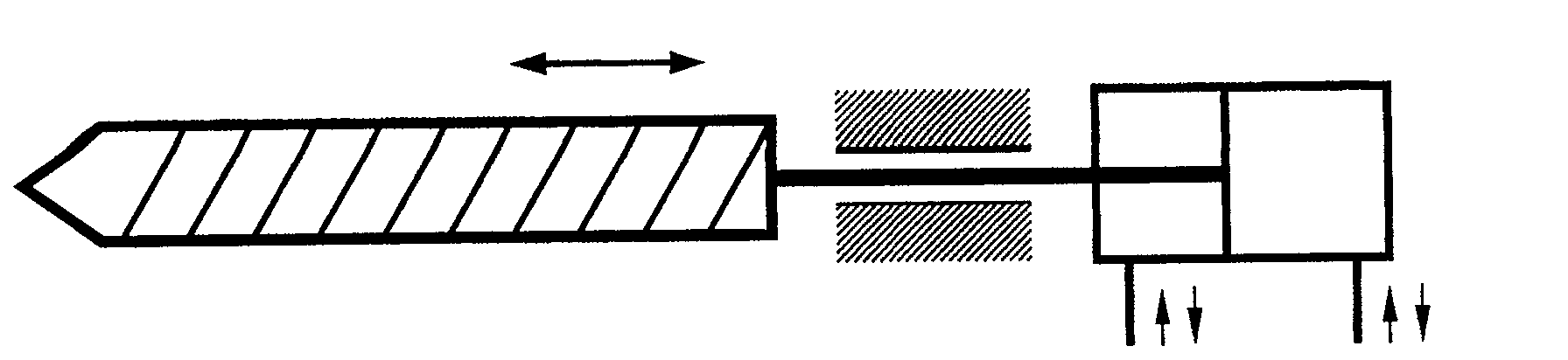
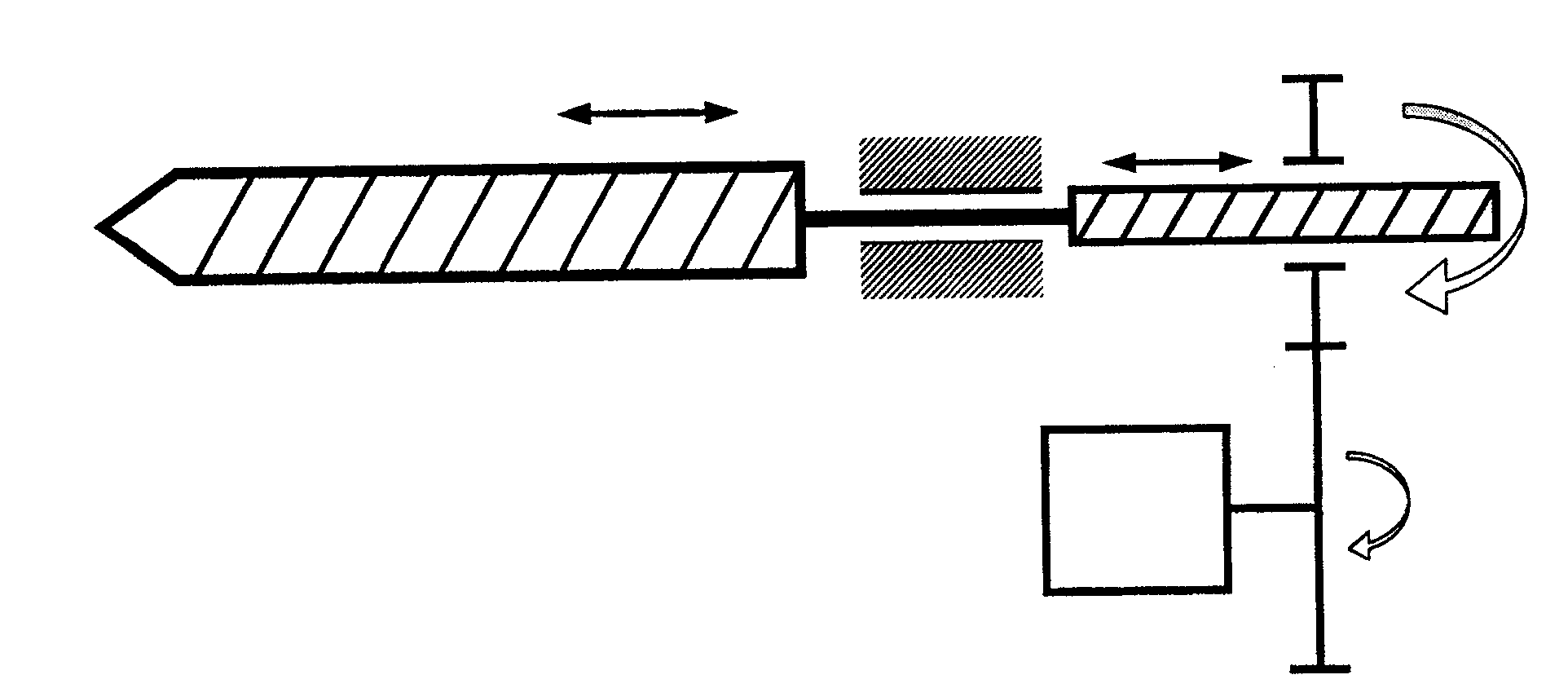
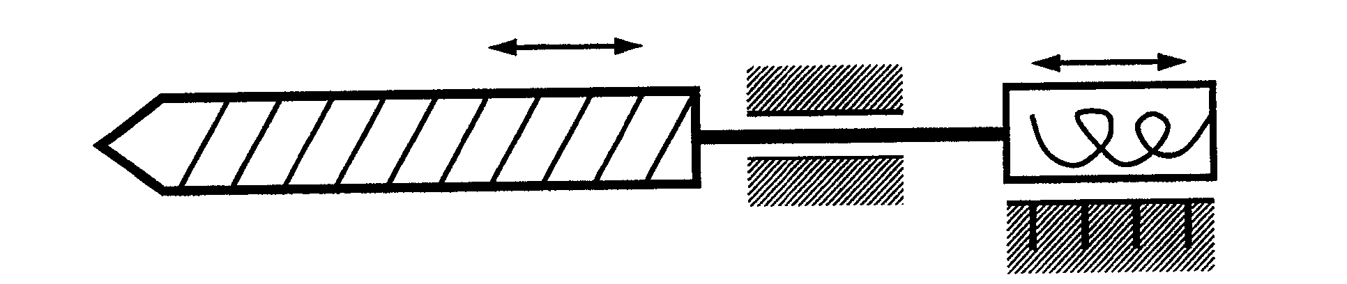
[0029] The specific structure of the present invention is as Figure 5 to Figure 9 shown by Figure 5 and Figure 6 It can be seen that the dynamic injection system of the injection molding machine includes an injection barrel 1, a screw 2, and an injection drive mechanism. The screw 2 extends into the injection barrel 1, and the injection drive mechanism is a crank vibration injection mechanism. The ends are connected; the crank vibration injection mechanism is as Figure 7 ~ Figure 9 As shown, it includes three crank drive assemblies, and the three crank drive assemblies are arranged in phases of 120° (see Figure 9 ), and is connected with the synchronous drive, and the synchronous drive simultaneously drives each crank drive assembly to move 120° phase cycle, the synchronous drive can be the drive shaft 3 of the same motor, and the crank drive assembly is as Figure 7 and Figure 8 As shown, it includes an injection plunger barrel 4, a plunger 5, and a crank assembly 6...


PUM


Abstract

The invention provides a dynamic injection system for an injection molding machine, which includes an injection barrel, a screw, and an injection drive mechanism. The screw extends into the injection barrel. connected; the crank vibrating injection mechanism includes several crank drive assemblies, the several crank drive assemblies are arranged in phases with each other, and are connected with the synchronous drive components. The vibration injection method realized by the dynamic injection system of the injection molding machine is to inject the material melts separately by the crank vibration injection mechanism with a certain phase, and then mix the material melts together before injecting, directly introducing the vibration effect into the material melts. The present invention introduces vibration effect without additional vibration generating device in the injection process, so that the physical properties of the product and the energy-saving effect of the molding process are significantly improved, and it has the advantages of simple and reasonable structure, low cost, convenient control, and easy large-scale promotion Advantages of using.

Description

technical field [0001] The invention relates to polymer dynamic injection technology, in particular to a dynamic injection system of an injection molding machine and a vibration injection method thereof. Background technique [0002] In the existing injection molding machine, in order to realize the reciprocating linear motion of the injection screw, the following four types of injection mechanism structures are generally used: (1) Use the oil cylinder to directly drive the screw to reciprocate (see figure 1 ); this scheme has low cost and has been used for decades at home and abroad; but this technology uses hydraulic oil as the transmission medium, resulting in large energy consumption, oil pressure pollution, and slow response. (2) Use the ball screw to drive the screw, and use the motor to drive the screw nut to realize the reciprocating motion of the rolling screw (similar structure figure 2 ); compared with the first scheme, this scheme has fast response speed, relat...

Claims


Application Information

Patent Timeline
Patent Type & Authority Patents(China)
IPC IPC(8): B29C45/46B29C45/54B29C45/17
Inventor 谭树发张贤宝
Owner 佛山市顺德区震德塑料机械有限公司
Why Eureka
Try Eureka