Self-powered sensor
A sensor and self-powered technology, applied in the field of sensors, can solve the problems of reduced magnetoelectric conversion efficiency and energy output capability, low quality factor, large loss, etc., to achieve increased resonant magnetoelectric conversion efficiency, improved quality factor, and improved magnetic The effect of the electrical voltage conversion factor
- Summary
- Abstract
- Description
- Claims
- Application Information
AI Technical Summary
Problems solved by technology
Method used
Image
Examples
Embodiment 1
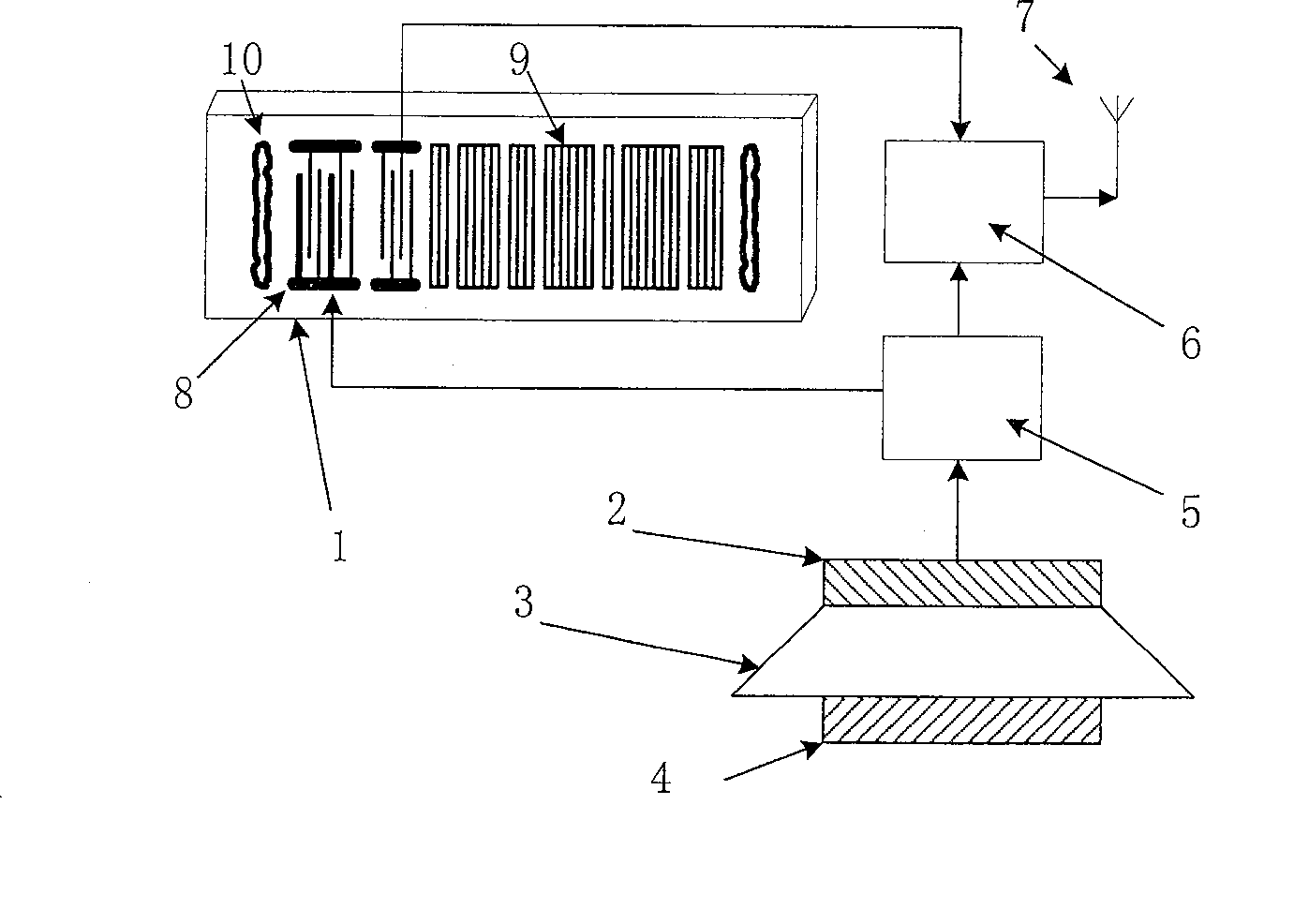
[0020] Embodiment 1: see figure 1 , a self-powered sensor, comprising a sensor 1 and a self-powered mechanism connected by a self-powered circuit 5, characterized in that: the self-powered mechanism is composed of a piezoelectric layer 2, a magnetostrictive layer 4 and a piezoelectric layer 2 and a magnetostrictive The enlargement mechanism 3 between the telescopic layers 4 constitutes. The output of the sensor is connected to the antenna 7 by the transmitting circuit 6 powered by the self-powered circuit to realize wireless signal transmission.
[0021] The above-mentioned self-powered circuit 5 adopts a conventional circuit.
[0022] The above-mentioned sensor 1 is a variety of surface acoustic wave sensors, usually composed of an interdigital transducer 8 on a piezoelectric substrate, a reflection grid 9 and a sound-absorbing material 10; the above-mentioned amplifying mechanism 3 is a mechanical quantity amplifying mechanism, such as a vibration amplifying Mechanism, For...
Embodiment 2
[0024] Embodiment 2: It differs from Embodiment 1 in that it adopts a different self-power supply mechanism, more specifically, the self-power supply mechanism adopts a different amplification mechanism.
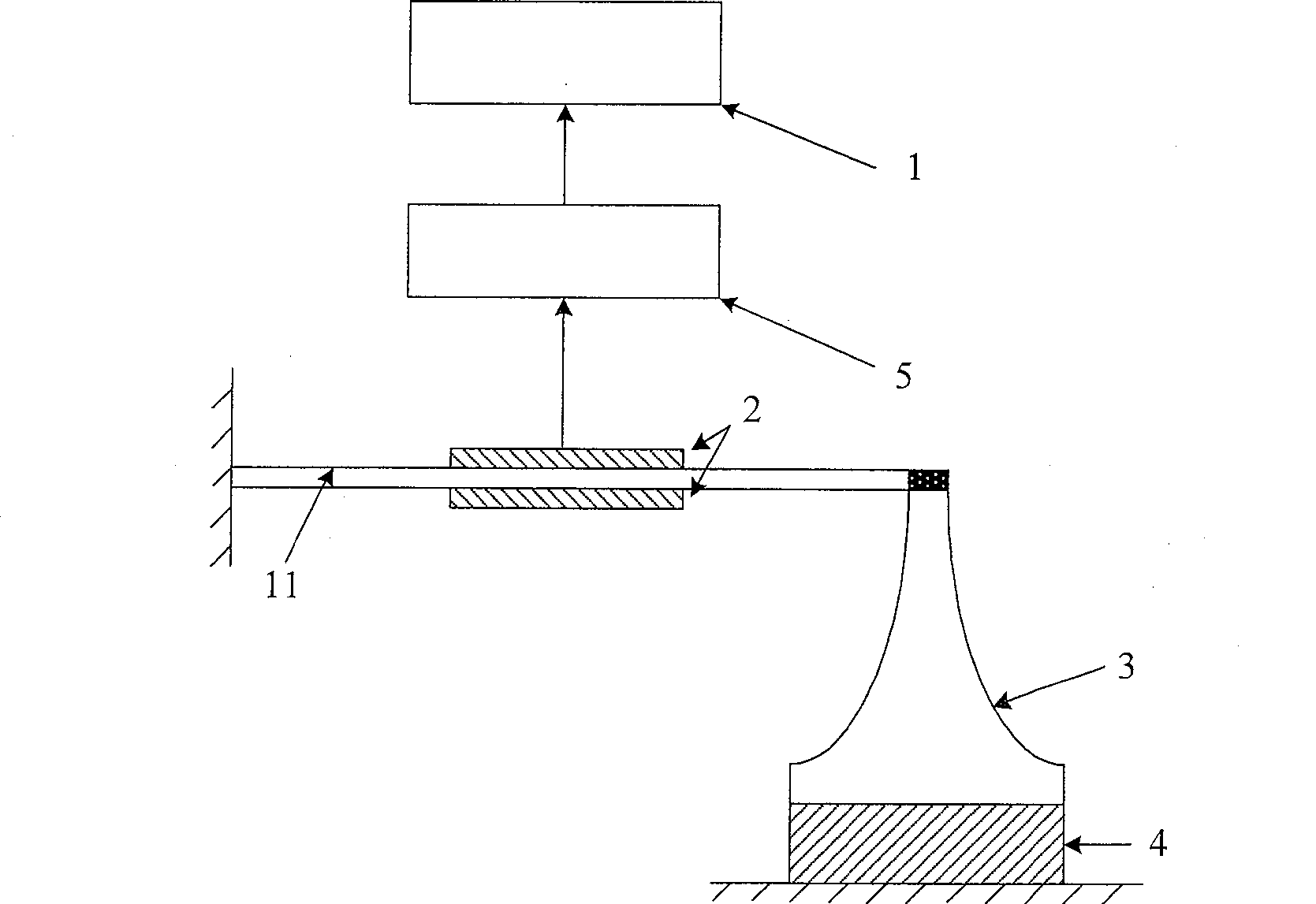
[0025] see figure 2 In this example, one end of the amplification mechanism 3 is connected to the magnetostrictive layer 4 , and the other end is connected to the piezoelectric layer 2 through the cantilever beam 11 , and the amplification mechanism 3 is arranged at the end point of the cantilever beam 11 .
[0026] The sensor described in this example transmits the strain amplification of the magnetostrictive material to the end point of the cantilever beam 11 due to the amplification mechanism 3 of the self-power supply mechanism, so that the strain of the cantilever beam 11 is correspondingly amplified, thereby also making the piezoelectric layer 2 The output amplification improves the magnetoelectric conversion efficiency and the energy supply capacity of the system.
Embodiment 3
[0027] Embodiment 3: It differs from Embodiment 1 in that it adopts a different self-power supply mechanism, more specifically, the self-power supply mechanism adopts a different amplification mechanism.
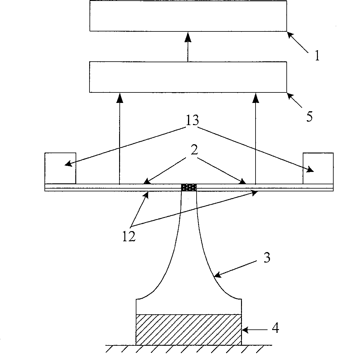
[0028] see image 3 In this example, one end of the amplification mechanism 3 is connected to the magnetostrictive layer 4 , and the other end is connected to the piezoelectric layer 2 through the resonant beam 12 , and the amplifying mechanism 3 is arranged at the midpoint of the resonant beam 12 .
[0029] In order to obtain a better resonance effect, mass blocks 13 are added at both ends of the resonant beam 12, which further improves the sensitivity of the system.
PUM
 Abstract
Description
Claims
Application Information
 - R&D
- Intellectual Property
- Life Sciences
- Materials
- Tech Scout
- Unparalleled Data Quality
- Higher Quality Content
- 60% Fewer Hallucinations
Browse by: Latest US Patents, China's latest patents, Technical Efficacy Thesaurus, Application Domain, Technology Topic, Popular Technical Reports.
© 2025 PatSnap. All rights reserved.Legal|Privacy policy|Modern Slavery Act Transparency Statement|Sitemap|About US| Contact US: help@patsnap.com


