
Air cylinder type injection valve

An injection valve and cylinder type technology, applied in the field of injection valves, can solve problems such as switch failure, rolling oil waste, and gas valves not working normally, and achieve easy maintenance, lower requirements for gas source pressure, and prevent oil and gas channeling Effect

Inactive Publication Date: 2009-09-16
CHINA NON-FERROUS METALS PROCESSING TECH CO LTD
View PDF5 Cites 1 Cited by
  • Summary
  • Abstract
  • Description
  • Claims
  • Application Information

AI Technical Summary

Problems solved by technology

From a structural point of view, the thin-film injection valve relies on the movement of the diaphragm to realize the switch and seal. During use, due to assembly or diaphragm damage, the switch failure and poor sealing often occur, and rolling oil will escape into the compressed air and follow the compression. Air enters the air valve, causing waste and pollution of rolling oil
If the rolling oil has impurities, it will also cause the air valve to not work properly
Therefore, due to its structure, processing and assembly, film materials and other reasons, the performance and life of the thin-film jet valve are difficult to meet the requirements of the roll cooling control.
[0004] In order to replace this thin-film injection valve, the applicant applied for a cylinder-type injection valve with the patent number ZL200620125640 on December 4, 2006, which has greatly improved performance and service life, but it needs to be disassembled and repaired from the rear end of the injection beam

Method used


Image

  • Air cylinder type injection valve
  • Air cylinder type injection valve
  • Air cylinder type injection valve

Examples


Embodiment Construction

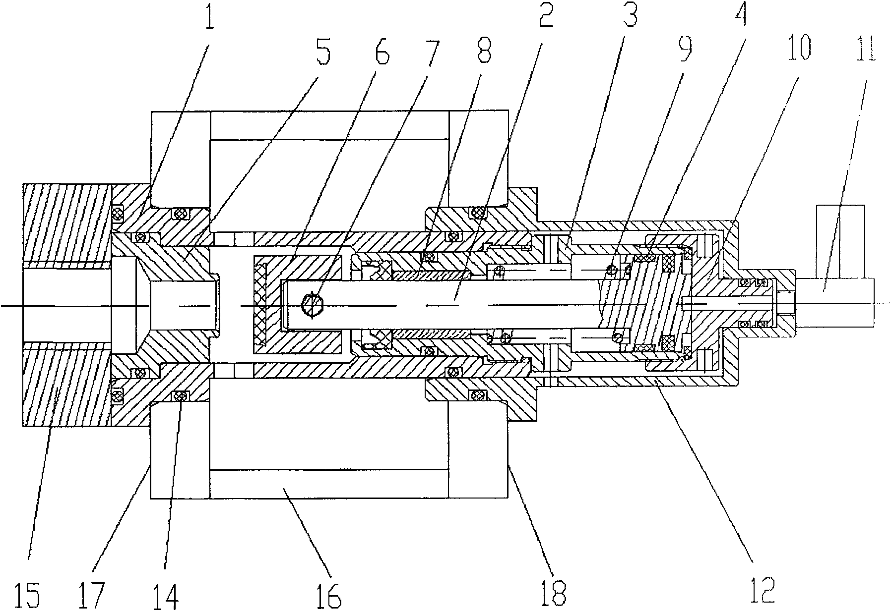
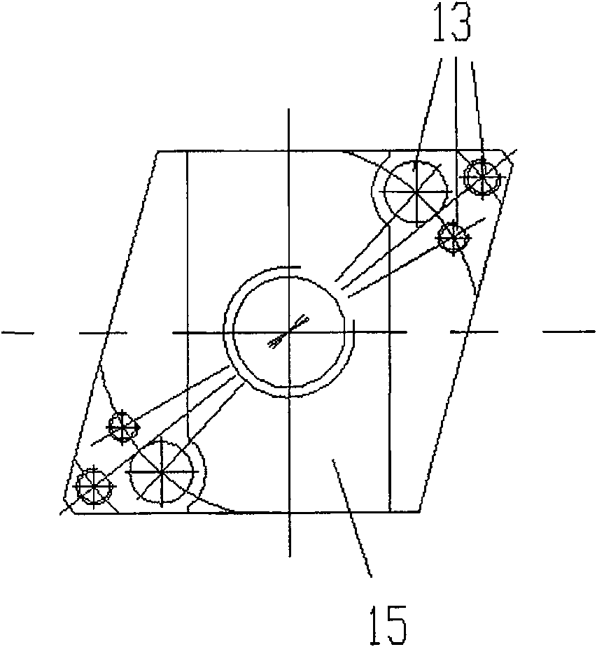
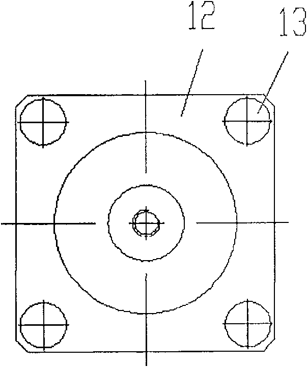
[0023] Such as figure 1 , 2 , 3, the present invention discloses a cylinder-type injection valve, which is attached to the injection beam 16 and installed. The entire injection valve consists of a valve seat 1, a valve core 2, a cylinder block 3, a guide belt 4, a valve head seat 5, a valve head 6. It is composed of cylindrical pin 7, copper sleeve 8, spring 9, cylinder head 10, valve seat 12, nozzle seat 15 and several sealing rings 14, etc. The valve seat 1 and the valve head seat 5 are fixedly connected to each other, the valve core 2 and the valve head 6 can move relative to the valve head seat 5, the valve core 2 is slidingly arranged inside the cylinder block 3, and the cylinder head 10 is fixed on the cylinder block 3 one end.

[0024] The nozzle seat 15 and the valve seat 1 are fixedly connected by screws 13 and then fixed to the front end 17 of the injection beam 16 together. The valve seat 1 passes through the injection beam 16 and extends into the inside of the v...


PUM


Abstract

The invention provides a cylinder type injection valve, which comprises a valve seat and a valve head seat fixedly connected to each other, and a valve core and a valve head which can move relative to the valve head seat, and the valve core is slidably arranged inside the cylinder body. The cylinder injection valve also includes an air nozzle seat and a nozzle seat. After the nozzle seat is fixedly connected with the valve seat, they are fixed on the front end of the injection beam together. The valve seat passes through the injection beam and extends into the air nozzle seat. The inside of the nozzle seat is fixed on the rear end of the injection beam. The invention relies on the movement of the piston to realize the switch, and the valve head is in a floating state, which ensures that the valve head is automatically guided when in contact with the valve seat, and the seal is reliable; the requirements for the pressure of the air source are reduced, and the air source does not need special treatment even if the pressure of the oil source is high. ;The entire injection valve except the nozzle seat can be taken out from the front end of the injection beam, which is convenient for maintenance and has a long service life.

Description

technical field [0001] The invention relates to a spray valve, in particular to a spray valve used as a process lubricating cooling system on a nonferrous metal processing plate, strip and foil rolling mill. Background technique [0002] Usually the valve is installed in the injection beam body, and the driving element of the valve can move between the open and closed positions according to the application. The traditional injection valve is used in the pressure accumulation type injection system. The valve body structure includes a control room, the injection medium is input into the control room, and the injection valve is installed on one side of the control room, and its outlet is connected with the throttling injection channel. The injection medium is in the The accumulation in the control chamber forms a high pressure, and when the injection valve is opened, the high-pressure medium is ejected from the injection channel. [0003] At present, in the domestic non-ferrou...

Claims


Application Information

Patent Timeline
Patent Type & Authority Patents(China)
IPC IPC(8): F16K1/00F16K31/122B21B45/02
Inventor 张海伟
Owner CHINA NON-FERROUS METALS PROCESSING TECH CO LTD
Learn More