Sound wave toothbrush and its rotation axle electric machine

A shaft motor and toothbrush technology, applied in the field of pendulum shaft motors, can solve the problems of difficulty in reducing the vibration inertia of the vibrator, harsh hardness consistency and precision, and difficulty in improving the practical working frequency, etc., to achieve simple overall structure and manufacturing process, and reliable performance , low cost effect

Active Publication Date: 2009-08-26
OASIS GLOBAL
View PDF8 Cites 1 Cited by
  • Summary
  • Abstract
  • Description
  • Claims
  • Application Information

AI Technical Summary

Problems solved by technology

In actual production and application, the power unit has very high requirements on the consistency of the vibration system, and has very strict requirements on the consistency and precision of the material and hardness after processing. The volume is also large, and the portability is limited to a certain extent, and the practical working frequency is also difficult to develop to a higher end.
[0009] A sonic toothbrush driven by a linear motor. The toothbrush works at two low-frequency frequencies. The main frequency is 250Hz to complete the linear movement of the brush head up and down. The other sub-frequency is 330Hz to complete the torque output, but the sub-frequency is weak. , the two actions are synthesized to form a spiral motion output. The power output is a moving iron resonant linear motor, which is small in size, but due to structural limitations, it is difficult to reduce the vibration inertia of the vibrator, and it is difficult to increase the practical operating frequency. And the production Complex process

Method used


Image

  • Sound wave toothbrush and its rotation axle electric machine
  • Sound wave toothbrush and its rotation axle electric machine
  • Sound wave toothbrush and its rotation axle electric machine

Examples


Embodiment Construction

[0029] Further description will be made below in conjunction with the accompanying drawings.

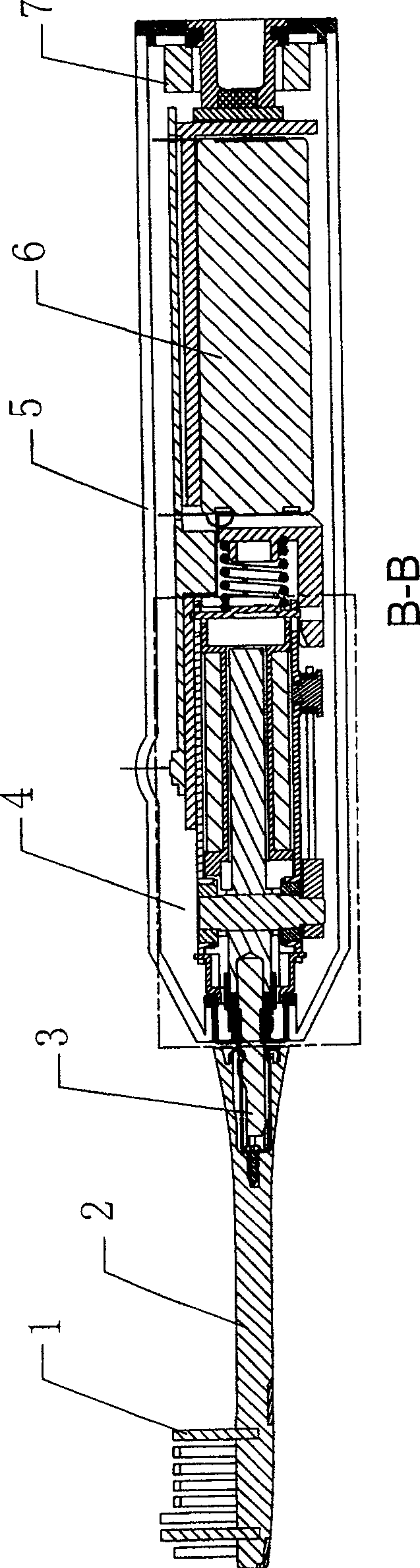
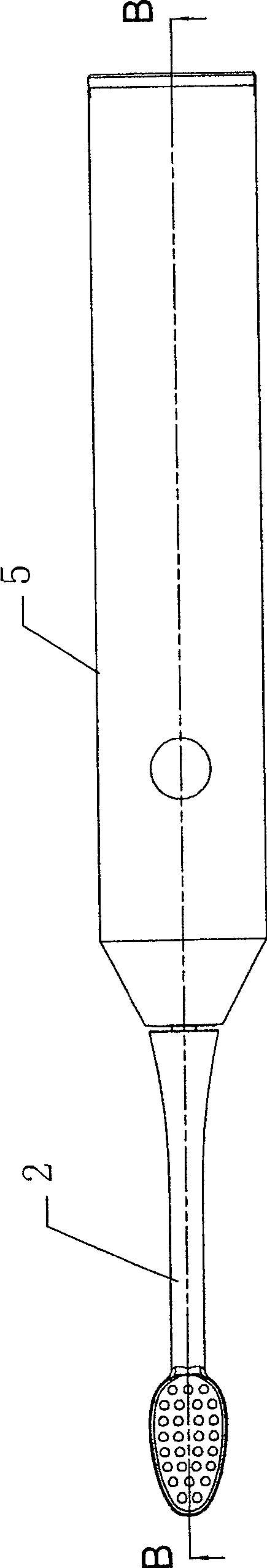
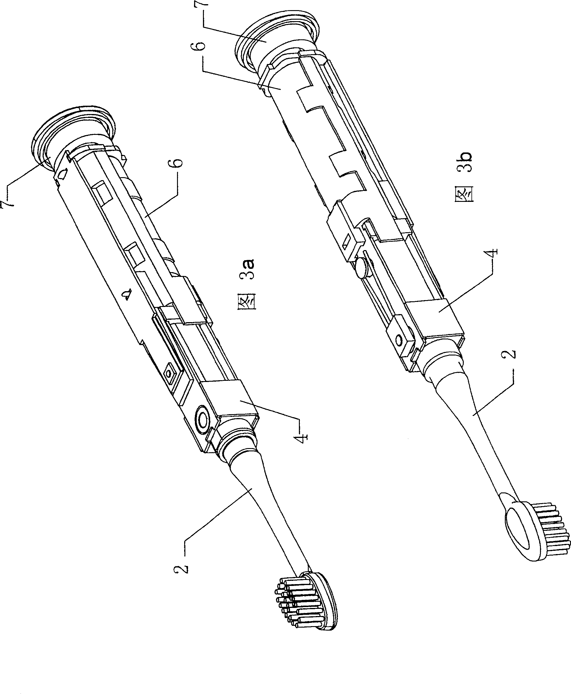
[0030] Such as Figure 1-6 As shown, the sonic toothbrush includes a toothbrush head and a toothbrush body 5 double as a handle. The toothbrush head includes a brush rod 2 and a bristle 1 planted at one end of the brush rod 2. The toothbrush body 5 includes a housing and a pendulum motor arranged in the housing. 4 and the motor drive device 6, 7 among the figure is the secondary induction coil for charging, the pendulum motor 4 contains the electromagnetic coil 49 outside the bracket 51, the bracket 51 and the pendulum shaft 50 positioned in the bracket 51 inner cavity, fixed at the bracket 51 end Two magnets 47, 48, two magnets 47, 48 are arranged side by side and opposite in polarity, the rotating shaft 41 is fixed on the swing shaft 50, and the swing shaft 50 is installed on the two splints 46 and 46' of the bracket 51 through the rotating shaft 41, The power output end of the pe...


PUM


Abstract

A sonic toothbrush, comprising a toothbrush head and a toothbrush body double as a handle, the toothbrush head includes a brush rod and bristles planted at one end of the brush rod, a swing shaft motor and a motor drive device are arranged in the toothbrush body, the swing shaft motor includes a bracket, and a The electromagnetic coil and the pendulum shaft located in the inner cavity of the bracket, two magnets are fixed at the end of the bracket, the pendulum shaft is installed on the bracket through the rotating shaft, the power output end of the pendulum shaft is connected with the toothbrush head, and the other end of the pendulum shaft is close to the two magnets, A frequency adjustment device for adjusting the swing frequency of the pendulum shaft is arranged on one side of the shaft motor. The vibration frequency of the toothbrush head of the toothbrush is increased to 350-550 Hz compared with 250 Hz of the conventional sonic toothbrush, the intensity of the "cavitation" effect is obviously improved, and the tooth cleaning efficiency is obviously improved. It has low running noise, reliable performance, long service life and simple production process. Can be designed as a toothbrush suitable for children.

Description

technical field [0001] The invention relates to an electric toothbrush, in particular to a sonic toothbrush whose toothbrush head vibrates at a low audio frequency to achieve high-efficiency tooth cleaning by means of the "cavitation" effect and a pendulum motor used for the sonic toothbrush. Background technique [0002] The emergence of electric tooth cleaning appliances is expected to replace ordinary manual toothbrushes and dental floss, and efficiently clean plaque and tartar in the interdental spaces. It is easier to clean the food residue accumulated between the teeth and gums, but for the plaque and calculus firmly attached to the surface of the gums, the following two methods are generally used to clean: [0003] 1. Use abrasives to assist mechanical power to directly remove tartar and plaque. This method will cause wear on the surface of the gums. It should be used under the advice of a dentist and is not suitable for daily household use. [0004] 2. Use a certain...

Claims


Application Information

Patent Timeline
Patent Type & Authority Patents(China)
IPC IPC(8): A61C17/22A61C17/32A46B13/02
Inventor 李绍棠
Owner OASIS GLOBAL
Why Eureka
Try Eureka