a ship

A ship and hull technology, applied in ship propulsion, ship construction, ship parts, etc., can solve problems such as poor endurance and service life, loss of power source, complex structure, etc., to improve endurance and service life, improve The effect of low utilization rate and cost

Active Publication Date: 2020-09-25
ZHEJIANG OCEAN UNIV
View PDF6 Cites 0 Cited by
  • Summary
  • Abstract
  • Description
  • Claims
  • Application Information

AI Technical Summary

Problems solved by technology

Although the above-mentioned unmanned ship has better endurance and longer service life, the above-mentioned unmanned ship still has the following defects: 1. The source of its propulsion power is all based on converting solar energy or wind energy into electrical energy, Then use electric energy to provide propulsion power, and the energy will be consumed during the conversion process, resulting in low energy utilization.
2. The environment of the ocean is not as changeable and relatively harsher than that of the land, and it is easy to cause damage to the electronic control components, solar power generation components and wind power generation components. When the power supply is lost, the unmanned ship is quite Due to the loss of the power source, the propulsion and battery life can no longer be maintained, and the battery life and service life are still poor
3. The structure is complex, and the cost of solar power generation components and wind power generation components is high

Method used


Image

  • a ship
  • a ship

Examples


Embodiment 1

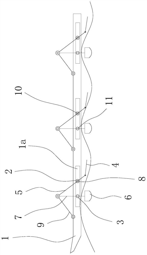
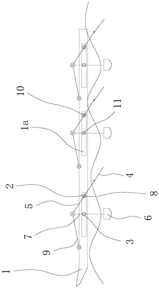
[0020] Such as figure 1 and 2 As shown, the ship includes a hull 1 and several groups of paddle assemblies arranged along the length direction of the hull 1. Both sides of the hull 1 are provided with several guide grooves 1a along the length direction of the hull 1, and the guide grooves 1a are along the length of the hull 1. direction, and each guide groove 1a is correspondingly connected with a group of the above-mentioned paddle assemblies.

[0021] The paddling assembly comprises a slide part one 2, a slide part two 3, a paddle plate 4, a connecting rod one 5, a connecting rod two 9, a lifting rod 7 and a buoyancy box 6. The first sliding piece 2 and the second sliding piece 3 are slidably connected in the corresponding guide groove 1a and can slide along the length direction of the hull 1. There is a gap between the first sliding piece 2 and the second sliding piece 3 and the groove wall of the guide groove 1a. Slider 1 2 is located behind slider 2 3, and guide sleeve ...

Embodiment 2

[0025]The structure of this embodiment is basically the same as that of Embodiment 1, the difference being that the paddle 4 and the connecting rod one 5 are hinged through the hinge shaft and between the paddle 4 and the connecting rod one 5, there is also a paddle 4 capable of limiting Limiting plate that swings forward about a hinge. The design of the limit plate makes the paddle board only rotate backwards, while the forward rotation is limited, so as to ensure that the paddle board 4 will not produce resistance to the forward movement of the ship, and can generate thrust on the water, thereby driving the ship forward move.


PUM


Abstract

The invention provides a ship, and belongs to the technical field of machinery. The problems that the energy utilizing rate is low, and the cruising ability is poor in existing ships are solved through the ship. The ship comprises a ship body and a plurality of groups of paddle assemblies arranged in the length direction of the ship body, the paddle assemblies comprise first sliding parts, secondsliding parts, paddle plates, first connecting rods, lifting rods and floating boxes, the first sliding parts and the second sliding parts are correspondingly and slidably connected to the two sides of the ship body and can slide in the length direction of the ship body, the first sliding parts are located on the rear parts of the second sliding parts, one ends of the lifting rods penetrate through the second sliding parts and are fixed to the floating boxes, the floating boxes are located on the lower part of the bottom of the ship body, the other ends of the lifting rods are hinged to one ends of the first connecting rods, the other ends of the first connecting rods are hinged to the paddle plates, thus swinging forwards of the paddle plates is limited, the first connecting rods are hinged to the first sliding parts through hinging parts, and the first connecting rods slidably penetrate through the hinging parts. A mechanical design mode of wave energy drive propelling is directly adopted, and thus the utilizing rate of energy and the cruising ability are improved, and the service life is prolonged.

Description

technical field [0001] The invention belongs to the technical field of machinery and relates to a ship. Background technique [0002] Unmanned ships have the advantages of reducing labor costs, saving energy and reducing consumption, and reducing accidents, and are widely used in the fields of observation of the marine environment, collection of experimental samples, and maritime cruising. Existing traditional unmanned ships need to carry a large amount of energy in order to ensure a good endurance and propulsion capability. As a result, due to the limitation of energy, it brings many difficulties to long-term and large-scale observation and experimental sampling of the environment. . [0003] In order to solve the above problems, for example, Chinese patent application (application number: 201820197769.0) discloses an unmanned ship including a hull, an electronic control component installed on the hull, including a power module, a solar power generation component, includin...

Claims


Application Information

Patent Timeline
Patent Type & Authority Patents(China)
IPC IPC(8): B63B35/00B63H19/04
CPCB63B35/00B63B2035/006B63H19/04Y02T70/5236
Inventor 鲁晓东张晨
Owner ZHEJIANG OCEAN UNIV
Why Eureka
Try Eureka