
Knife feeding mechanism suitable for processing compressor crankshaft box and repeatedly adjustable in feeding speed

A feed speed technology for the crankshaft and main shaft of a compressor, which is applied to metal processing machine parts, metal processing, and metal processing equipment. Improve processing efficiency, facilitate large-scale promotion, and reduce production costs

Pending Publication Date: 2017-11-24
HUANGSHI HUADAN MACHINE MFG
View PDF17 Cites 0 Cited by
  • Summary
  • Abstract
  • Description
  • Claims
  • Application Information

AI Technical Summary

Problems solved by technology

The structure of the crankcase is complex, because a large number of sound-absorbing chambers are required, so it is necessary to process multiple through-holes and the continuous holes of each sound-absorbing chamber. This multi-cavity continuous hole structure is difficult to process, and due to the existence of multiple stages of idling travel, its processing efficiency lower
[0004] At present, for the machining of the crankcase, most of the conventional processing methods use a fast-forward approach to the workpiece and then convert it into a work-feed. Once the work is done until the machining is completed, the intermittent idle strokes (that is, useless strokes) are all completed at the work-feed speed, wasting Processing beats reduce production efficiency
In order to overcome the above-mentioned defects, a technical solution using a servo slide has appeared in the prior art. In this solution, processing is carried out by controlling the conversion between multiple fast-forward and multiple work-forward, although the problem of low production efficiency can be overcome to a certain extent. , but the structure and size of this servo slide are large, the control system is complicated, the cost is high, and the maintenance is complicated and the cost is high

Method used


Image

  • Knife feeding mechanism suitable for processing compressor crankshaft box and repeatedly adjustable in feeding speed
  • Knife feeding mechanism suitable for processing compressor crankshaft box and repeatedly adjustable in feeding speed
  • Knife feeding mechanism suitable for processing compressor crankshaft box and repeatedly adjustable in feeding speed

Examples


Embodiment Construction

[0026] In order to make the object, technical solution and advantages of the present invention clearer, the present invention will be further described in detail below in conjunction with the accompanying drawings and embodiments. It should be understood that the specific embodiments described here are only used to explain the present invention, not to limit the present invention.

[0027] In addition, the technical features involved in the various embodiments of the present invention described below can be combined with each other as long as they do not constitute a conflict with each other.

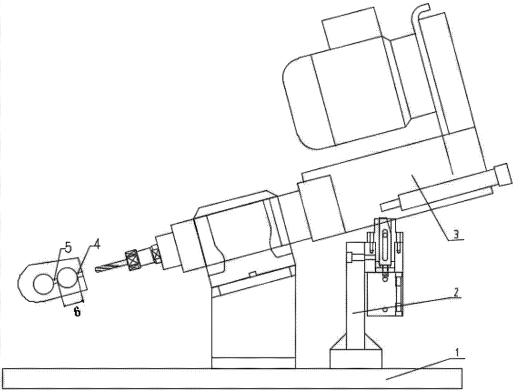
[0028] figure 1 It is a schematic diagram of the overall structure of a multi-feeding mechanism according to an embodiment of the present invention. Such as figure 1 As shown, the multi-feeding mechanism of the embodiment of the present invention includes a working surface 1 , a fixture 2 and a pneumatic drilling head 3 .

[0029] Such as figure 1 As shown, both the fixture 2 and th...


PUM


Abstract

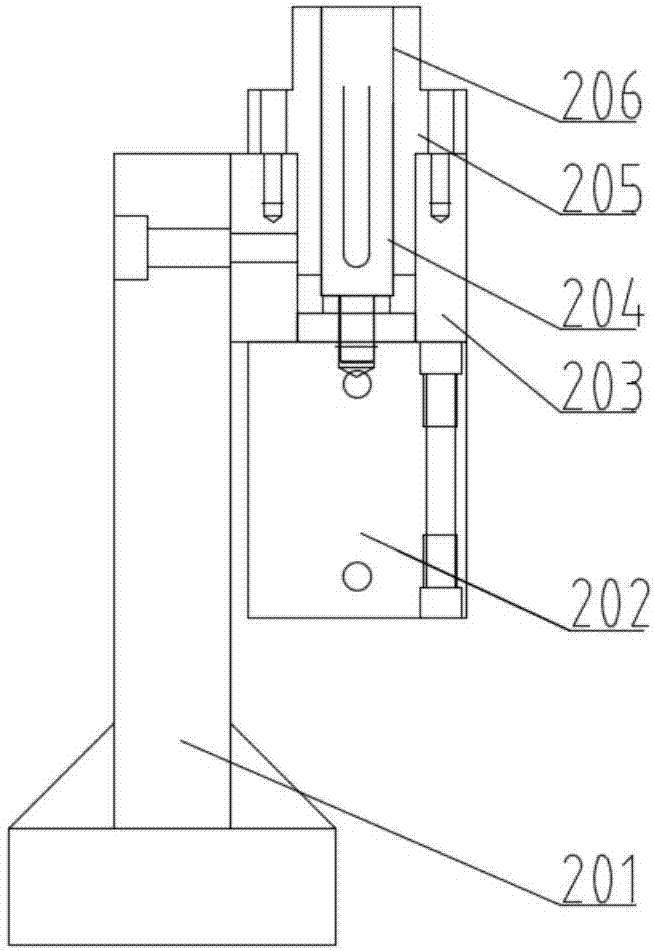
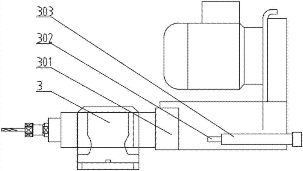
The invention discloses a knife feeding mechanism suitable for processing a compressor crankshaft box and repeatedly adjustable in feeding speed. The knife feeding mechanism comprises a drilling head arranged on a workbench and an adjustable clamp arranged on the workbench, a knife is arranged at the front end of the drilling head, the middle of the drilling head is set up on the workbench, a driving motor is arranged at the rear end of the workbench, the adjustable clamp comprises a fixing seat arranged on the workbench, a fixing block arranged on the fixing seat and provided with a central through hole and a cylinder arranged on a baseplate of the fixing block, a sliding nail is arranged at the top of a piston rod, a fixed retaining face is arranged on the sliding nail, a step lining sleeves the central through hole in the upper portion of the fixing block, and the sliding nail can directionally and linearly move back and forth in the lining under action of the cylinder to drive the fixed retaining face to ascend or descend so as to realize switching and adjusting of feeding speed of a spindle of the drilling head. A blocking part is utilized to control knife feeding speed to be switched between quick feeding and normal feeding so as to control the feeding speed to be repeatedly adjustable, and efficient and stable processing of the crankshaft box is realized; the knife feeding mechanism is small in structural size and simple to control.

Description

technical field [0001] The invention belongs to the field of compressors, and more specifically relates to a tool feed mechanism with multiple adjustable feed speeds suitable for machining crankcases of compressors. Background technique [0002] The compressor is the heart of the refrigeration system. It inhales low-temperature and low-pressure refrigerant gas from the suction pipe, drives the piston to compress it through the movement of the motor, and discharges high-temperature and high-pressure refrigerant gas to the exhaust pipe to provide power for the refrigeration cycle. Thus realizing the refrigeration cycle of compression-condensation-expansion-evaporation. [0003] At present, the compressors of household refrigerators are mostly volumetric compressors, which can be divided into reciprocating compressors and rotary compressors. The main components include crankcases, pistons, crankshafts, connecting rods and motors. The crankcase serves as the base of the entire ...

Claims


Application Information

Patent Timeline
IPC IPC(8): B23Q5/28B23Q5/52
CPCB23Q5/28B23Q5/52B23Q2005/005
Inventor 马权钱文勤金礼朱杰
Owner HUANGSHI HUADAN MACHINE MFG
Learn More