Power supply circuit of an electric and corresponding control method
A power supply voltage and circuit technology, applied in the field of power supply circuits, can solve the problems of complex structure, high cost and high harmonic components of the interrupter control circuit
- Summary
- Abstract
- Description
- Claims
- Application Information
AI Technical Summary
Problems solved by technology
Method used
Image
Examples
Embodiment Construction
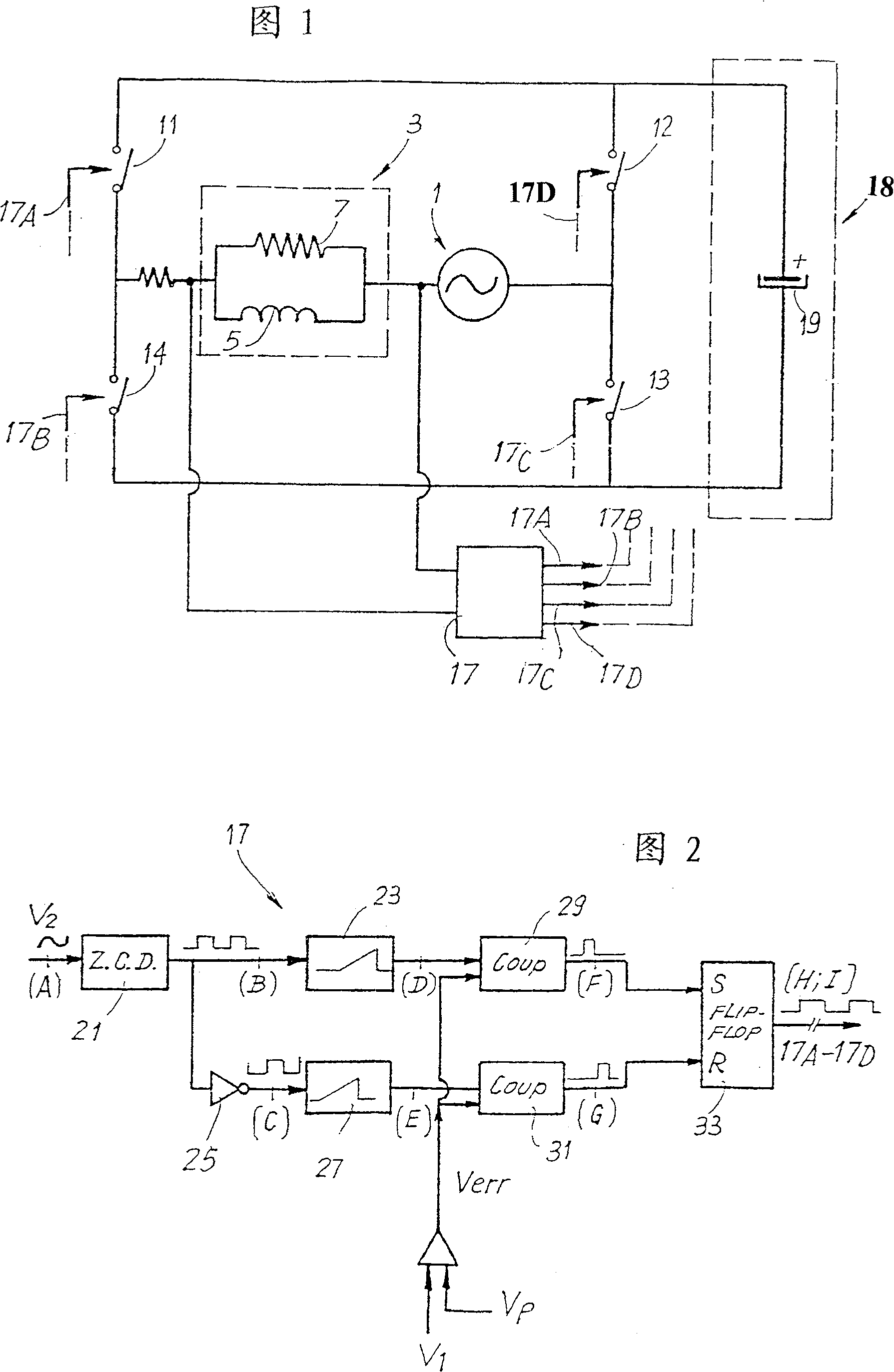
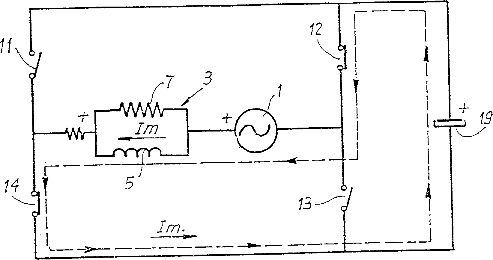
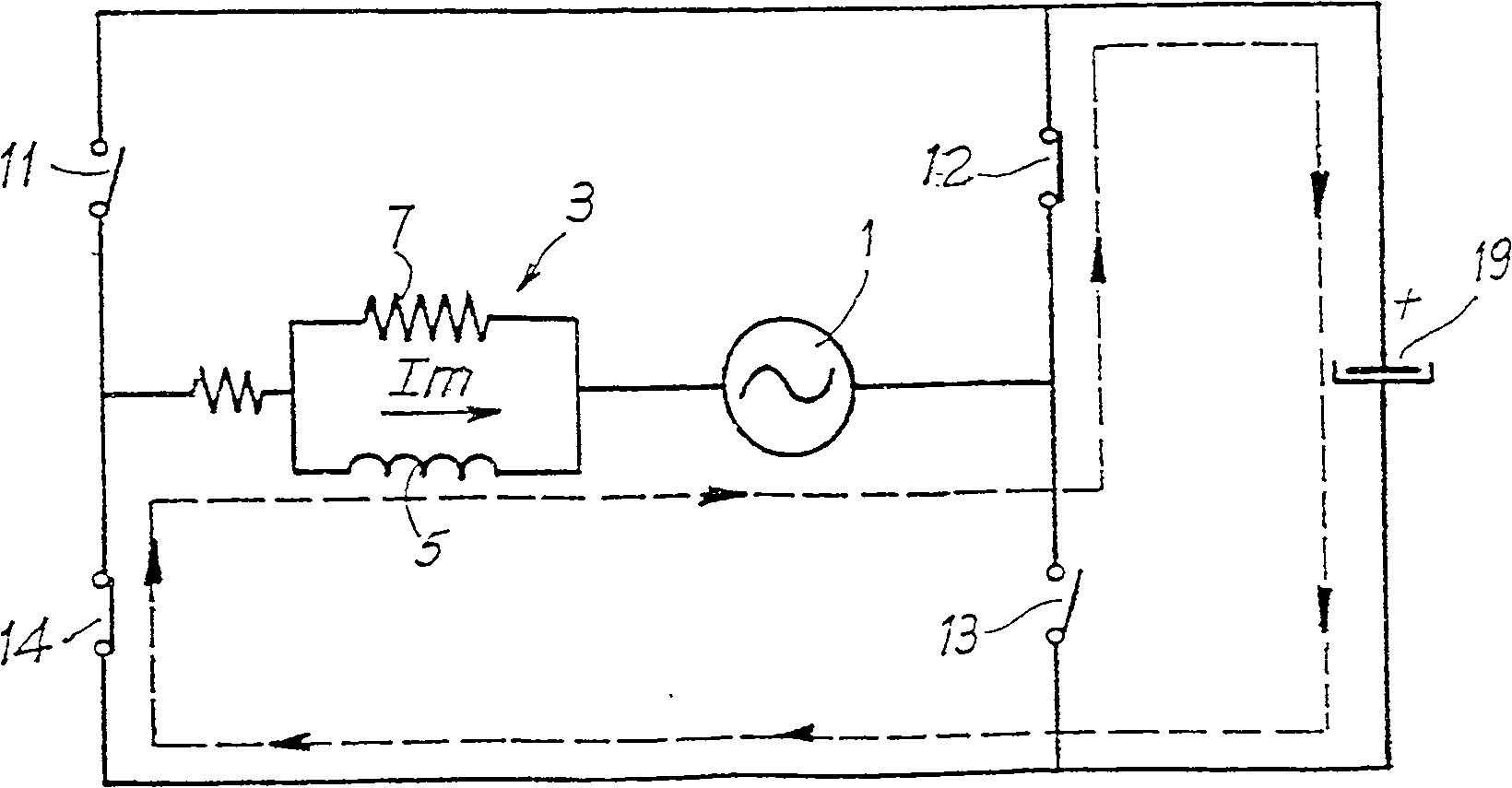
[0025] figure 1 Briefly shows the constant voltage power supply circuit for single-phase asynchronous motor. Reference 1 denotes an AC voltage source, including for example a power grid, a generator device or other sources. The number 3 designates in a general way the motor, which is schematically represented by an inductor 5 and a resistor 7 connected in parallel.
[0026] The motor 3 and the voltage source 1 are connected in a full bridge comprising controlled switches 11, 12, 13 and 14, for example comprising the same number of MOSFETs or other switching devices controlled by a control logic 17 which outputs 17A-17D To toggle switches 11-14.
[0027] A DC branch 18 comprising a storage capacitor 19 is connected in parallel with the bridge 11-14. As will be clear from the following description, the control logic 17 controls the switching of the switches 11-14 according to the voltage across the motor 3 and the phase of the power supply voltage. This control method produce...
PUM
 Abstract
Description
Claims
Application Information
 - R&D
- Intellectual Property
- Life Sciences
- Materials
- Tech Scout
- Unparalleled Data Quality
- Higher Quality Content
- 60% Fewer Hallucinations
Browse by: Latest US Patents, China's latest patents, Technical Efficacy Thesaurus, Application Domain, Technology Topic, Popular Technical Reports.
© 2025 PatSnap. All rights reserved.Legal|Privacy policy|Modern Slavery Act Transparency Statement|Sitemap|About US| Contact US: help@patsnap.com


