
Temperature control device of electric cooker

A technology for temperature control devices and rice cookers, applied in heating devices, temperature control, non-electric variable control, etc., can solve problems such as enlarged faults, short service life, and shortened service life of electric cookers, so as to avoid man-made damage , cost reduction effect

Inactive Publication Date: 2009-08-05
李强
View PDF3 Cites 0 Cited by
  • Summary
  • Abstract
  • Description
  • Claims
  • Application Information

AI Technical Summary

Problems solved by technology

[0003] 1. The elastic force of the magnetic shrapnel switch is easily lost under the action of external force and high temperature, so that the switch cannot be turned on and fails
2. The contact resistance of the switch increases to 10 ohms to tens of ohms, and it will burn out due to the passage of a large current
3. If the magnetically controlled shrapnel switch encounters water or other reasons for leakage, the isolation insulating sheet will be burned and carbonized, and the fault will continue to expand after the current passes through, burning the electric heating plate, wires, plastic parts, etc.
4. The warmer is easy to sinter, and it will continue to expand the fault until the electric heating plate is burned or the ultra-high temperature protector is blown
Due to the shrapnel switch in the traditional rice cooker (especially the 900-2500W high-power rice cooker), the heat preservation thermostat works in a high-temperature vicious cycle state, and the service life is short. It is easily damaged in harsh environments such as insects and cockroaches, which shortens the service life of the rice cooker and brings trouble and loss to people for unnecessary maintenance.

Method used


Image

  • Temperature control device of electric cooker
  • Temperature control device of electric cooker

Examples


Embodiment Construction

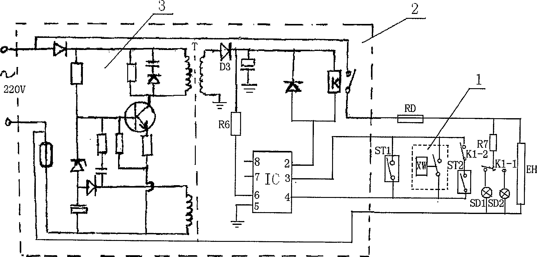
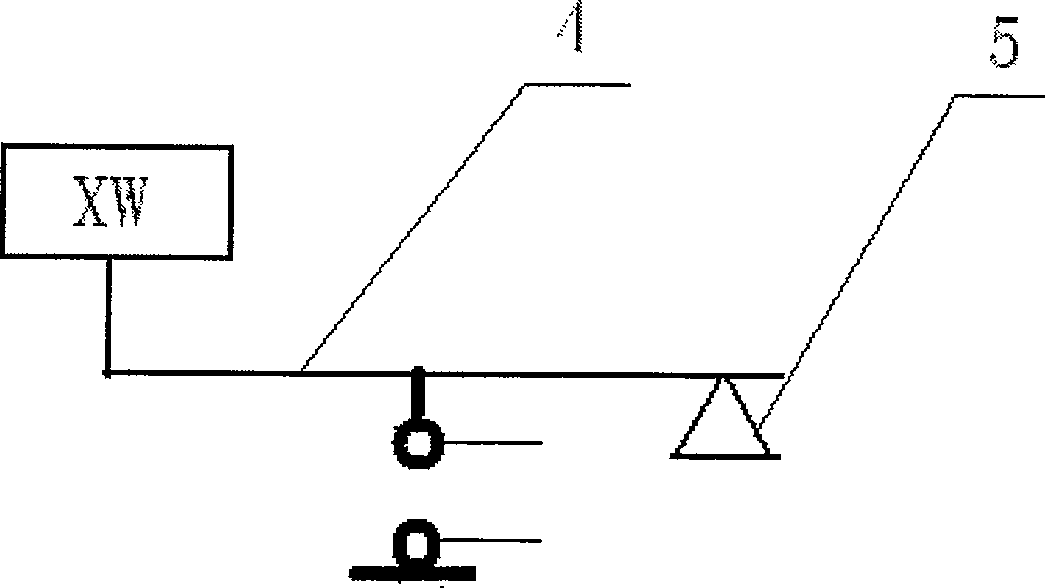
[0031] Such as figure 1 , figure 2 As shown, a temperature control device for an electric rice cooker includes, a power supply, a magnetic control switch 1 located in the pot, a heat preservation device connected in parallel with a group of contacts K-2 of the cooking and heat preservation switch K1 and the magnetic control switch 1 The device ST2 and the electric heating plate EH are located on the shell of the electric rice cooker and are provided with a controller 2 connected with the electric heating plate EH and the magnetic control switch 1 . Described controller 2 also can be located at the plug place of electric cooker power line. The controller 2 includes a power supply circuit 3, a transformer T, an integrated circuit IC, and a relay K. The power supply is connected to the primary phase of the transformer T through the power supply circuit 3. One end of the secondary side of the transformer T is grounded, and the other end is respectively connected to the relay thr...


PUM


Abstract

The invention discloses a temperature control device for an electric rice cooker, which includes a power supply, a magnetic control switch located in the cooker, a warmer connected in parallel with the magnetic control switch through a transfer switch, and an electric heating plate. The shell of the rice cooker is provided with a controller connected with the electric heating plate and the magnetic control switch. After adopting the split temperature control device, the original defects and deficiencies of the traditional electric rice cooker are completely solved. The damage probability of the electric rice cooker is greatly reduced. The magnetic control switch, temperature controller, and temperature limiter in the rice cooker can work normally without damage in the harsh environment, thus greatly prolonging the service life of the rice cooker, and it is not easy to be damaged by man-made. The controller avoids the high temperature outside the pot, and can be made small and exquisite. In case of damage, people can replace it as simply and quickly as changing plugs and sockets. By adopting the temperature control device for the electric rice cooker, a safe, reliable and long service life electric rice cooker can be refitted or produced simply, conveniently and at low cost.

Description

technical field [0001] The technical solution to be protected by the present invention relates to a temperature control device for an electric rice cooker. Background technique [0002] At present, the magnetically controlled shrapnel switch and the normally closed type insulator in the temperature control device of the traditional rice cooker are powered by the elastic contact of the shrapnel. It will gradually increase in harsh environments such as humidity and oily smoke. The large current passed by the switch will cause arcing when it is disconnected, so the contact resistance is easier to increase. The contact resistance is large, and when a large current passes through, it will generate heat, and the elastic force of the shrapnel will decrease accordingly. The elastic force will decrease, the contact will be poor, and the contact resistance will increase. In this way, the heat of the switch will increase, and the heat will increase. The elastic force is further reduce...

Claims


Application Information

Patent Timeline
Patent Type & Authority Patents(China)
IPC IPC(8): A47J36/24G05D23/00
Inventor 李强
Owner 李强
Learn More