
Chargeable battery

A battery, charging and discharging technology, applied in the direction of secondary battery manufacturing, battery pack components, battery circuit devices, etc., can solve the problems of connection reliability decline, compatibility defects, and batteries that cannot adapt to structurally diverse electrical products, etc. Achieve the effect of enhanced anti-loss performance and reliable protection

Inactive Publication Date: 2009-07-29
GUANGZHOU ZHANHUI ELECTRONICS
View PDF3 Cites 0 Cited by
  • Summary
  • Abstract
  • Description
  • Claims
  • Application Information

AI Technical Summary

Problems solved by technology

[0002] Rechargeable batteries are characterized by high energy density, high discharge voltage, light weight, small size, and portability. They are widely used in the fields of electronics, home appliances, and IT products. Generally, rechargeable batteries are used in When charging is required, the charging process must be completed through a specific charger. The charger usually includes a suitable battery box, which is positioned and electrically connected by spring compression. Since the battery box is pressed by a spring, the use Over time, the elasticity of the spring will deteriorate, which will reduce the reliability of the connection and make it difficult to ensure long-term normal operation
[0003] On the other hand, currently commonly used batteries generally have a positive pole at one end and a negative pole at the other end. There is only one power supply method, and there are various battery boxes in small appliances and IT products on the market. Therefore, a single power supply The battery of this type obviously cannot adapt to the needs of such structurally diverse electrical products, and its compatibility has defects.

Method used


Image

  • Chargeable battery
  • Chargeable battery
  • Chargeable battery

Examples


Embodiment Construction

[0022] The present invention will be further described below in conjunction with the accompanying drawings and examples of the description:

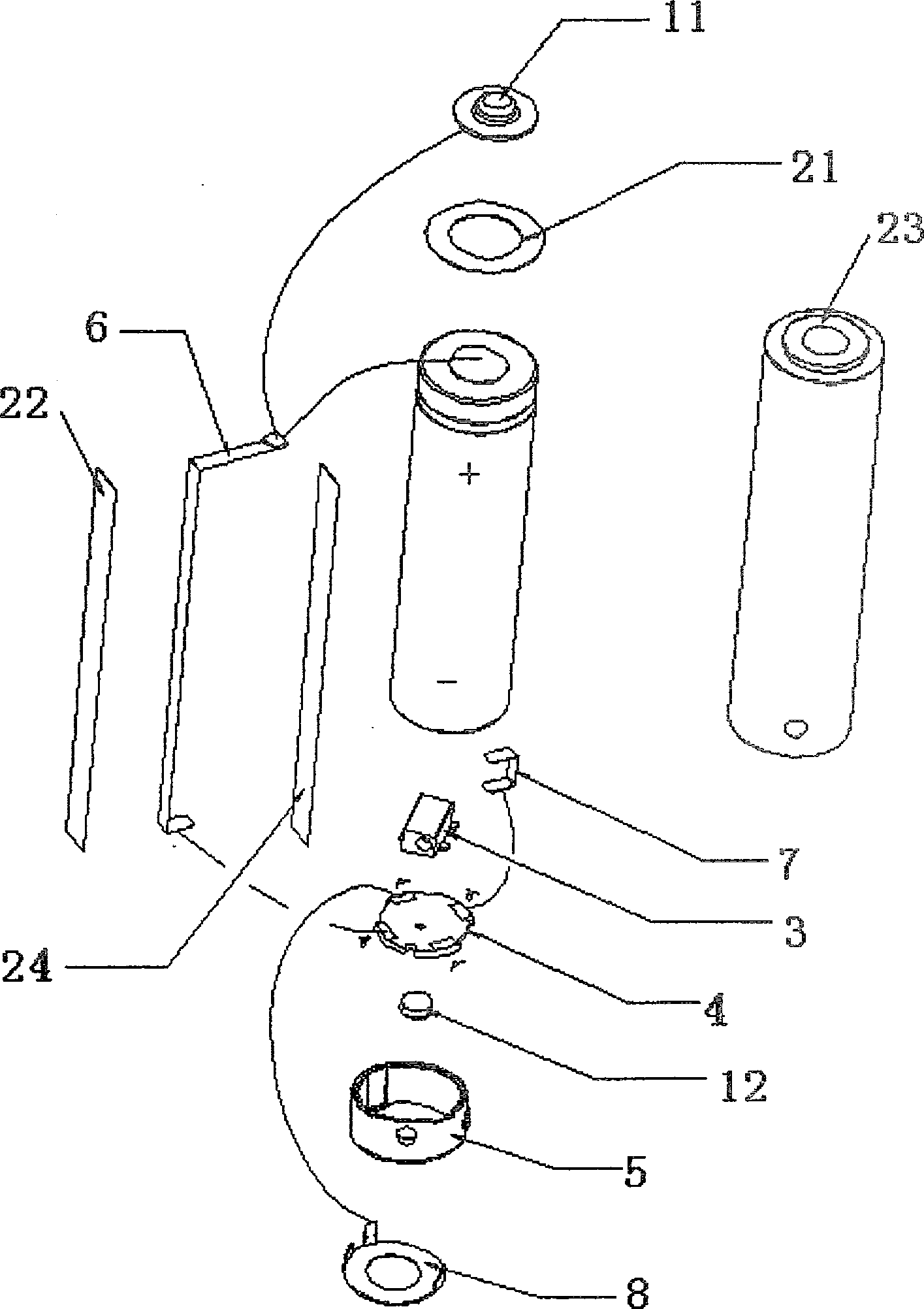
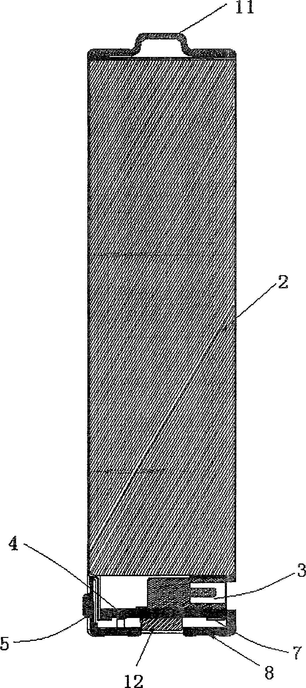
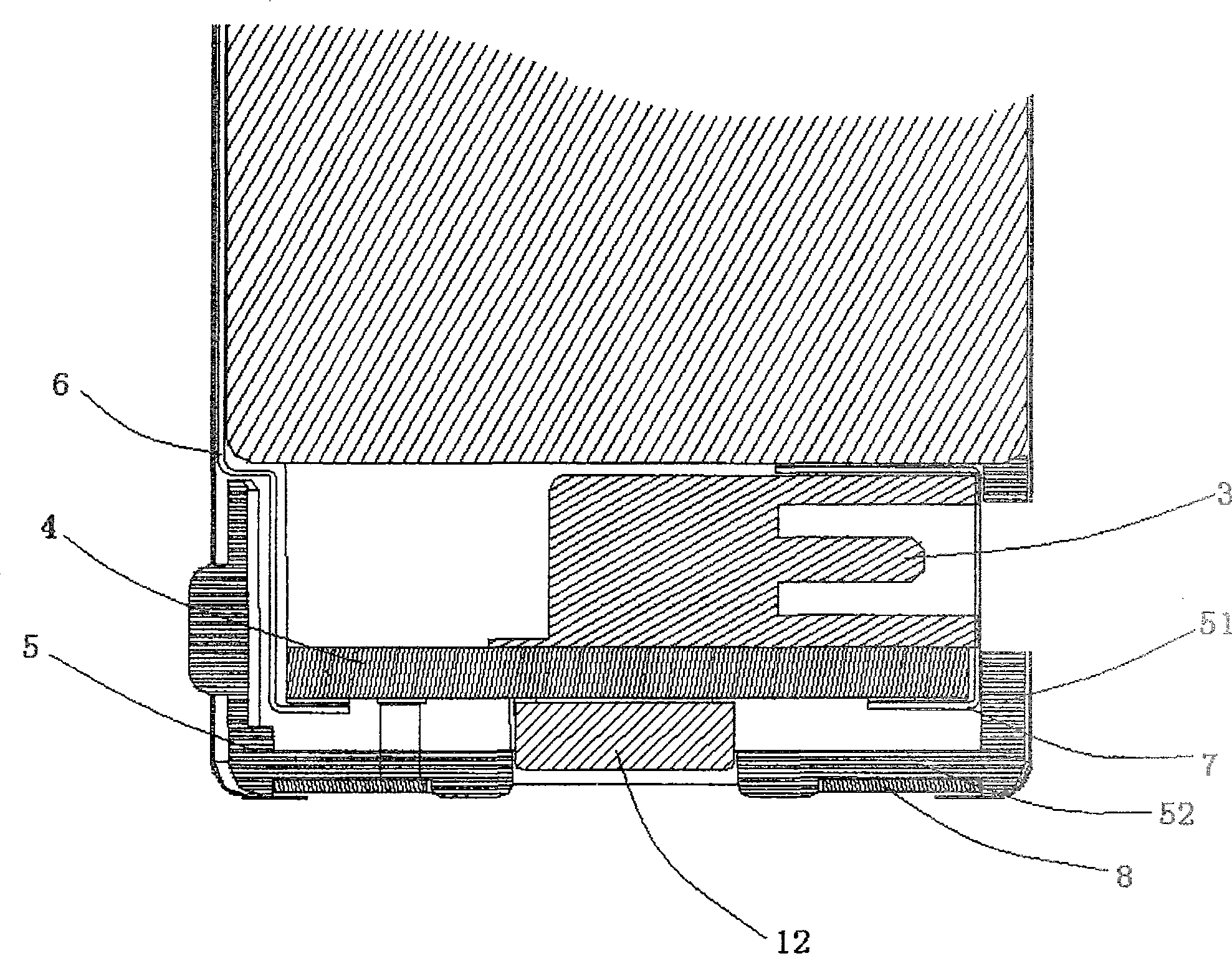
[0023] like figure 1 and figure 2 As shown, the rechargeable battery involved in the present invention includes: at least one battery cell 2, a casing 23 wrapping the battery core 2, a positive electrode and a negative electrode 8 of the battery, and a charging and discharging circuit including a charging and discharging protection circuit. The charging and discharging circuit is integrated on a circuit board 4 and is encapsulated in the battery case 23 together with the battery cell 2. The positive electrode contact of the battery is connected to the circuit board 4 through a positive nickel sheet 6. The positive nickel sheet is separated from the shell 23 and the battery cell 2 by a first fireproof paper 22 and a second fireproof paper 24, and the first positive electrode 11 sheet and the battery cell 2 are separated by a third firep...


PUM


Abstract

The present invention discloses a chargeable battery which comprises at least one battery cell(2), an outer cover(23) for enclosing the battery cell(2), the anode and cathode(8) of the battery, an electricity charging and discharging circuit comprising a protecting circuit of the electricity charging and discharging circuit. The electricity charging and discharging circuit is integrated into a circuit board(4) and is encapsulated into the outer cover(23) of the battery together with the battery cell(2). Wherein, the sidewall surface of the battery is concave provided with an electricity charging socket(3), the two terminals of which are respectively connected with the anode and cathode of the electricity charging and discharging circuit. Through combining the two anodes and cathodes at the two terminals of the battery, the rechargeable battery disclosed in the present invention can provide two power supply modes. Through adopting the rechargeable lithium battery structure, the invention has the advantages of convenient electric charging operation and taking, as well as compatible with the structures of various electric appliance products.

Description

technical field [0001] The invention belongs to the technical field of rechargeable batteries, and in particular relates to a secondary battery with an improved structure of a charging socket. Background technique [0002] Rechargeable battery is a kind of high energy density, high discharge voltage, light weight, small size and easy to carry. It is widely used in the fields of electronics, home appliances and IT products. When charging is required, the charging process should be completed through a specific charger. The charger usually includes a suitable battery box, which is positioned and electrically connected by spring compression. Since the battery box adopts spring compression, use Over time, the elasticity of the spring will deteriorate, the reliability of the connection will be reduced, and it is difficult to ensure normal operation for a long time. [0003] On the other hand, the general structure of the currently used battery is that one end of the battery is po...

Claims


Application Information

Patent Timeline
Patent Type & Authority Patents(China)
IPC IPC(8): H01M10/04H01M10/44H01M2/34H01M2/26H01M2/20H01M2/02H02J7/00H01M50/244H01M50/247H01M50/284H01M50/50H01M50/531H01M50/572
CPCY02E60/10Y02P70/50
Inventor 李智董超祺
Owner GUANGZHOU ZHANHUI ELECTRONICS
Learn More