
Mixed optical wavelet conversion method based on white light and monochromatic light

A technology of wavelet transform and monochromatic light, which is applied in the field of information optics, can solve problems such as unsatisfactory, obstacles to the development of monochromatic light optical wavelet transform systems, and inability to numerically reconstruct optical wavelet transform results.

Inactive Publication Date: 2009-07-22
CHONGQING UNIV
View PDF5 Cites 2 Cited by
  • Summary
  • Abstract
  • Description
  • Claims
  • Application Information

AI Technical Summary

Problems solved by technology

[0004] The monochromatic light optical wavelet transform system has its inherent disadvantages: coherent noise and speckle noise are serious, so the result of the monochromatic light optical wavelet transform is always speckle overlapping, which is hard to be unsatisfactory, and the noise problem becomes the monochromatic light optical wavelet Serious obstacle to transformation system development
However, there is currently no construction of an optical wavelet filter that satisfies the above requirements
Therefore, numerical reconstruction cannot be performed through optical wavelet transform results, which limits the application range of optical wavelet transform techniques

Method used

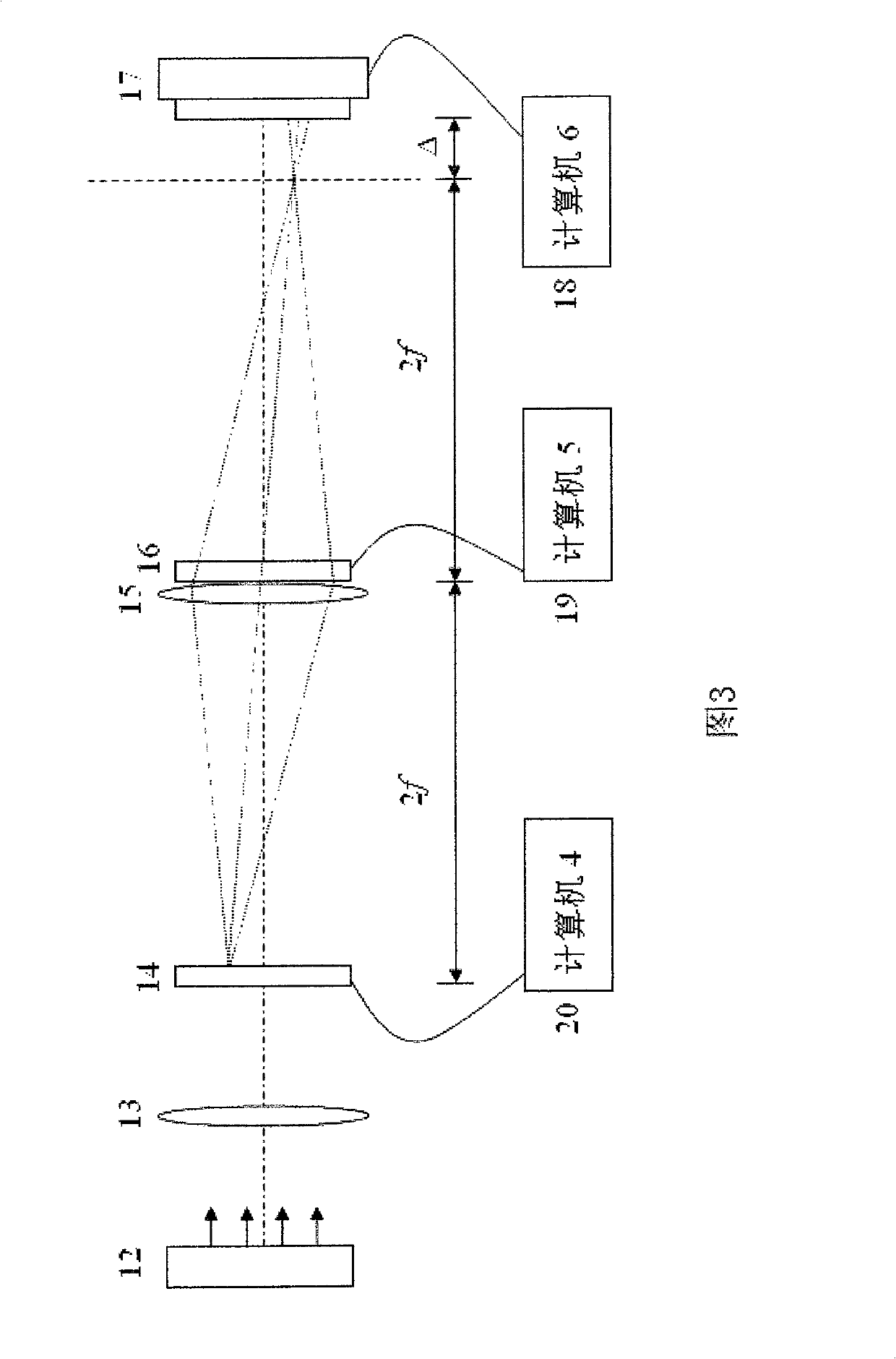

Image

  • Mixed optical wavelet conversion method based on white light and monochromatic light
  • Mixed optical wavelet conversion method based on white light and monochromatic light
  • Mixed optical wavelet conversion method based on white light and monochromatic light

Examples


Embodiment Construction

[0062] Embodiments of the present invention are described in further detail below in conjunction with the accompanying drawings:

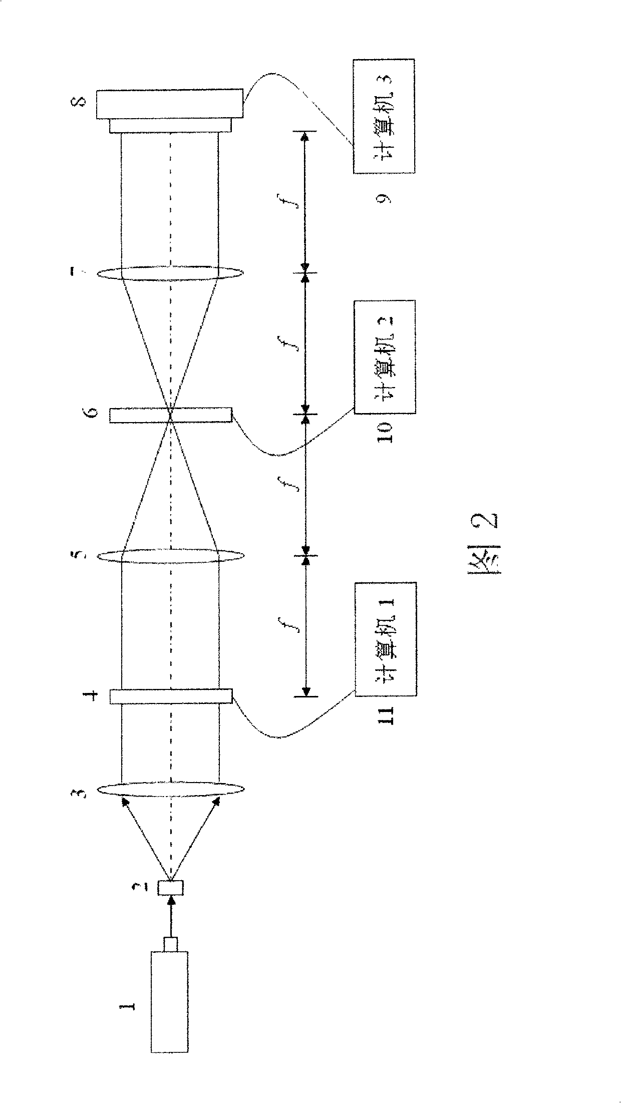
[0063] The structure of the optical wavelet transform system based on monochromatic light is shown in Figure 2. The helium-neon laser 1 is located 10 cm in front of the pinhole filter 2, and the pinhole filter 2 is located at the front focal plane of the collimator lens 3. The collimator lens 10cm behind 3, install the first electrical addressing spatial light modulator 4, the electrical addressing spatial light modulator 4 is located at the front focal plane of the first Fourier lens 5, the back focal plane of the Fourier lens 5 is connected to the second Fourier The front focal planes of the lens 7 converge at one place, where the second electrically addressable spatial light modulator 6 is installed, and the first CCD photocoupling device 8 is installed at the back focal plane of the second Fourier lens 7 . He-Ne laser 1, pinhole filter 2, colli...


PUM


Abstract

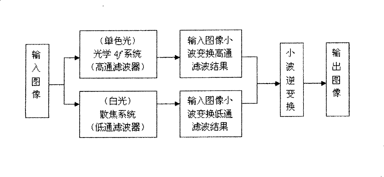
The invention relates to a hybrid optical wavelet transform method based on white light and monochromatic light, and constructs an optical wavelet filter. Firstly, the input image is passed through a monochromatic light optical wavelet transform system to realize high-pass filtering in optical wavelet transform, and the input The numerical result of the high-pass filtering of the image wavelet transform; the input image is passed through the white light optical wavelet transform system to realize the low-pass filtering in the optical wavelet transform, and the numerical result of the low-pass filtering of the input image wavelet transform is obtained; then the numerical result of the high-pass filtering is obtained The results and the numerical results of low-pass filtering are used to reconstruct the input image on the computer through the numerical algorithm of wavelet inverse transformation. The optical wavelet transform realized by this method can be applied to image compression. Compared with the traditional optical wavelet transform system based on monochromatic light, it can effectively overcome the coherent noise and speckle noise, and the quality of the image reconstructed by the optical wavelet transform realized by the system is obviously improved.

Description

technical field [0001] The present invention relates to the technical field of information optics, specifically, a hybrid optical wavelet transform method based on white light and monochromatic light and a corresponding optical wavelet filter construction method. Background technique [0002] Wavelet transform technology has good performance and has been widely used in the fields of image compression, signal processing, and image processing; however, the huge amount of calculation in its application restricts the further promotion of wavelet transform applications. Therefore, combining the optical method with the wavelet transform to form an optical wavelet transform method can greatly reduce the time spent on wavelet transform, which is of great theoretical and practical value. [0003] At present, optical wavelet transform has been used in edge extraction, feature extraction, pattern recognition and other fields, showing a good application prospect. However, the optical w...

Claims


Application Information

Patent Timeline
Patent Type & Authority Patents(China)
IPC IPC(8): G02B27/46H04N5/21G06T9/00
Inventor 田逢春韩亮李立曾孝平冯文江唐光菊于雯辉刘赛姬艳丽
Owner CHONGQING UNIV
Learn More