Welding joint for fuel tank

一种熔接接头、燃料箱的技术,应用在树脂熔接接头领域,能够解决熔接强度降低、防燃料渗透性和熔接强度劣化、熔接部防燃料渗透性劣化等问题,达到熔接强度保持、优良防水性、提高计算可靠性的效果

Inactive Publication Date: 2009-07-15
SUMITOMO RIKO CO LTD
View PDF4 Cites 0 Cited by
  • Summary
  • Abstract
  • Description
  • Claims
  • Application Information

AI Technical Summary

Problems solved by technology

[0034] However, the water resistance of EVOH is not always sufficient
Thus, there is a problem in this configuration that in the case where the weld is exposed to moisture for a long time, the weld will absorb moisture, resulting in deterioration of the fuel penetration resistance of the weld and a decrease in weld strength
Additionally, welded portion 250 of welded joint 248 is easily exposed to moisture
Therefore, in the case where the entire welded portion 250 is made of such a resin alloy material, fuel permeation resistance and weld strength may deteriorate over time.

Method used


Image

  • Welding joint for fuel tank
  • Welding joint for fuel tank
  • Welding joint for fuel tank

Examples


Embodiment Construction

[0074] Embodiments of the present invention will be described in detail below with reference to the accompanying drawings.

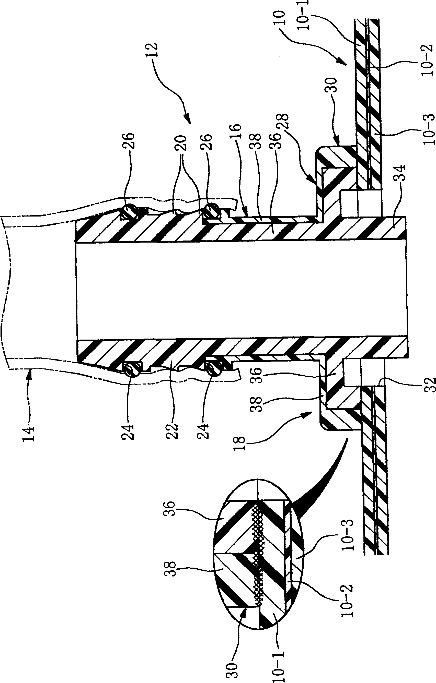
[0075] exist figure 1 In , reference numeral 10 denotes a resin fuel tank. In this embodiment, a resin fuel tank 10 has an outer layer member 10-1 and an inner layer member 10-3 made of HDEP resin. Further, the fuel tank 10 has a cross-sectional structure in which a thin barrier member 10-2 is sandwiched by an outer layer member 10-1 and an inner layer member 10-3.

[0076] Incidentally, the barrier member 10-2 also constitutes an inner layer with respect to the outer layer 10-1.


PUM


Abstract

A welding joint for a fuel tank includes a cylindrical portion and an annular weld portion. The weld portion has a multi-layer structure formed by layering an inner layer member made of a resin alloy material obtained by alloying a modified HDPE, to which a functional group having a high affinity to a hydroxyl group of EVOH is introduced, and EVOH, or by alloying the modified HDPE, normal HDPE and EVOH, and an outer layer member which uses the HDPE resin and / or modified HDPE resin and has high weldability to the fuel tank. Each of the inner and outer layer members is heat-welded to the fuel tank at a corresponding welding end surface. In a vicinity of at least one of the welding end surfaces of the inner outer layer members, a flow preventing portion that prevent a molten part of the inner layer member from flowing the outer layer member is provided.

Description

technical field [0001] The present invention relates to a resin joint for connecting a piping tube or a connector to a resin fuel tank, and more particularly to a resin welded joint which is welded to the fuel tank and constitutes a connecting portion. Background technique [0002] A fuel tank installed in a motor vehicle is integrally provided with a fitting for connecting the fuel tank to a pipe or a connector for guiding fuel injected from a filler port to the fuel tank. [0003] Hitherto, for example, rubber tubes (or rubber hoses) have been used as tubes for guiding fuel injected from a filler port to a fuel tank. However, in recent years, from the viewpoint of environmental protection, regulations for preventing fuel from permeating to the outside through hoses have become strict. Therefore, a rubber-resin composite material pipe composed of a rubber hose having a resin barrier layer, a rubber pipe made of fluororubber having fuel permeation resistance, or a resin pip...

Claims


Application Information

Patent Timeline
Patent Type & Authority Patents(China)
IPC IPC(8): B29C65/44B60K15/03
CPCB29C66/723B60K15/04B29C65/02B32B27/306B32B27/08B32B1/08B32B2605/00B29L2031/7172B29C66/326B29C66/131B60K15/03177B29C66/116B29C66/53247B32B2307/7265B29K2023/065B29C66/3282B29L2009/00B29K2023/086B29C66/322B29K2995/0067B29C66/112B32B7/08B32B27/32B29C66/8322B29C66/7234B29C66/71
Inventor 西山高广片山和孝仁木伸明
Owner SUMITOMO RIKO CO LTD
Why Eureka
Try Eureka