Composite reactive multilayer foil

A thin, reactive technology, applied in the field of freestanding multi-layer thin sheets, which can solve the problems of detachment, failure to successfully combine, and material difficulties.

Inactive Publication Date: 2009-07-15
THE JOHN HOPKINS UNIV SCHOOL OF MEDICINE
View PDF5 Cites 2 Cited by
  • Summary
  • Abstract
  • Description
  • Claims
  • Application Information

AI Technical Summary

Problems solved by technology

For example, many materials pose great difficulty and have not previously been successfully combined
In addition, methods that use reactive flakes as heat sources often result in the flakes detaching from the substrate during the reaction, thus weakening the bond.

Method used


Image

  • Composite reactive multilayer foil
  • Composite reactive multilayer foil
  • Composite reactive multilayer foil

Examples


example 1

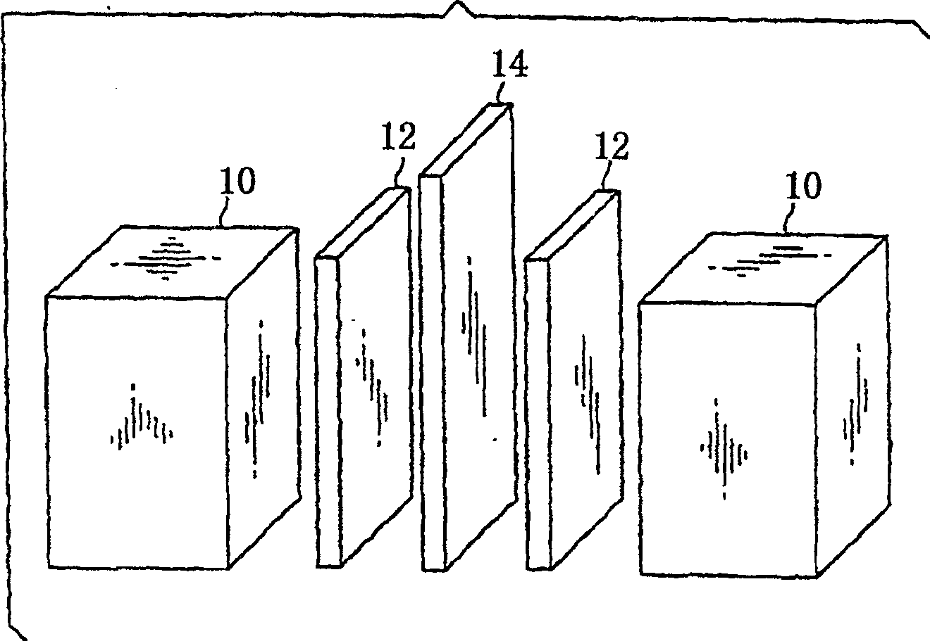
[0067] The reactive flakes of aluminum and nickel were formed by cold rolling a number of 5 μm nickel and aluminum flakes stacked together. Figure 6 Stack 61 is shown passing through press rollers 62A and 62B to make sheet 60 . The sheet can be cold rolled several times until the thickness of the layers is reduced to the desired value.

example 2

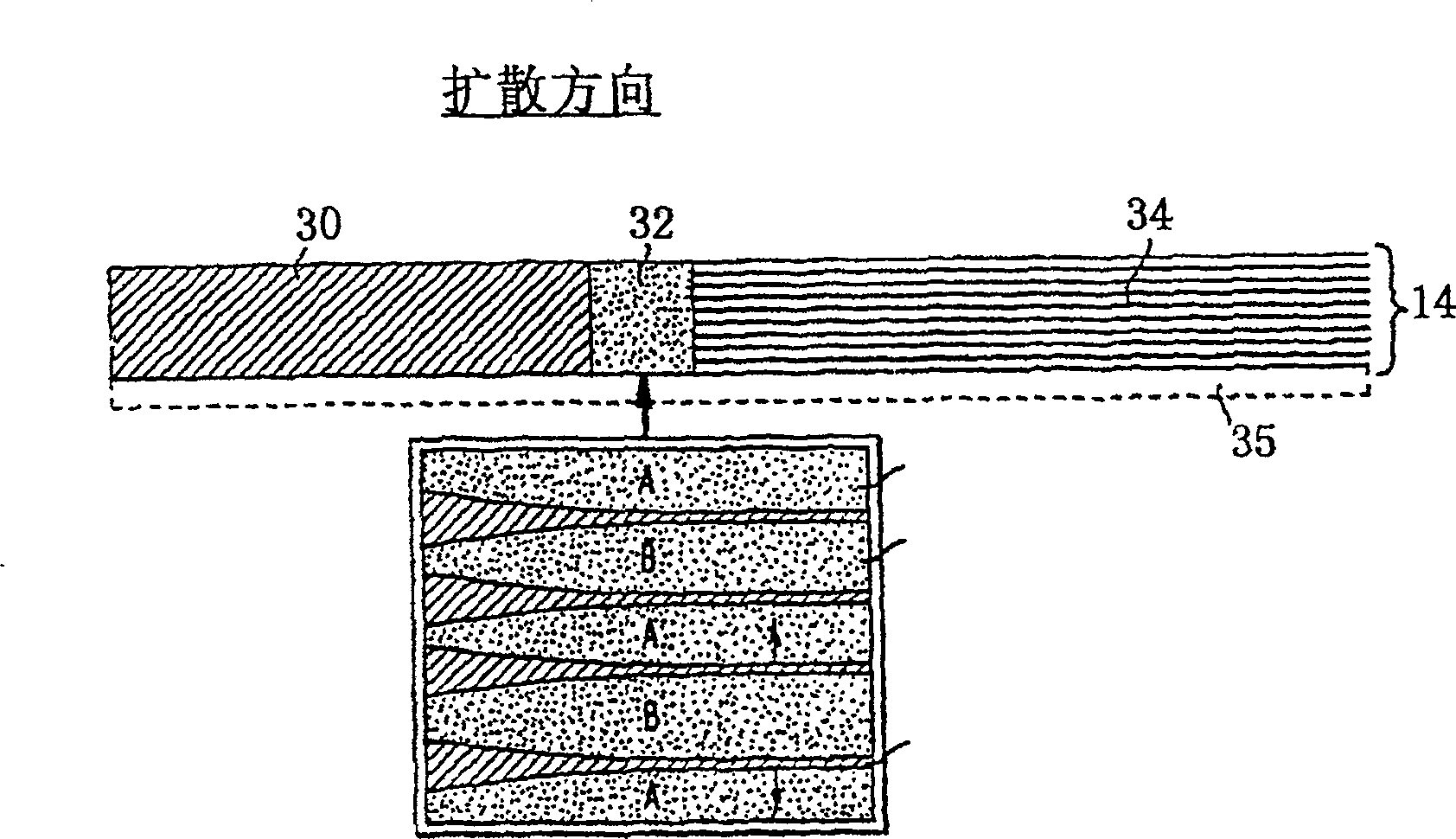
[0069] Rather than using a sheet composed of multiple layers of the same thickness, a composite sheet is used, where responsive multilayers of nanolayers are deposited on reactive microlayer sheets. Such as Figure 7 As shown, some portions of the layer 70 in the reactive flake 71 will be nanoscale (nanolayers) and other portions 72 will be micron-thick layers (microlayers). As noted above, the nanolayer will readily react and once the reaction begins, will self-diffuse along the length of the sheet without being snapped by melting of surrounding brazing layers or loose components. Thus, nanolayers can be considered as igniters of microlayers. The portion 72 with the microlayers cannot sustain a self-diffusion reaction at room temperature, but when heated by the adjacent nanolayer portion 70, it will maintain the reaction. The flakes may consist of alternating layers of aluminum and nickel.

example 3

[0071] In making these composite sheets, sheets of aluminum and nickel are calendered to form microlayer sections, and then nanolayer sheets are vapor deposited on either surface of the microlayer structure. Fabrication can also be done by vapor deposition of the entire composite, where microlayers are deposited at a higher rate without igniting the flakes or causing unacceptable mixing in alternating layers during deposition.


PUM

PropertyMeasurementUnit
Thicknessaaaaaaaaaa
Thicknessaaaaaaaaaa

Abstract

Reactive foils and their uses are provided as localized heat sources useful, for example, in ignition, joining and propulsion. An improved reactive foil (14) is preferably a freestanding multilayered foil structure made up of alternating layers (16, 18) selected from materials that will react with one another in an exothermic and self-propagating reaction. Upon reacting, this foil supplies highly localized heat energy that may be applied, for example, to joining layers, or directly to bulk materials that are to be joined. This foil heat-source allows rapid bonding to occur at room temperature in virtually an environment (e.g., air, vacuum, water, etc.). If a joining material is used, the foil reaction will supply enough heat to melt the joining materials. If no joining material is used, the foil reaction supplies heat directly to at least two bulk materials, melting a portion of each bulk, which upon cooling, form a strong bond. Additionally, the foil (14) may be designed with openings that allow extrusion of the joining (or bulk) material through the foil to enhance bonding.

Description

[0001] government concern [0002] This invention was made with Government support under Licenses DMR-9702546 and DMR-9632526, and through Military Laboratory / Advanced Materials Characterization Program Award No. 019620047. The government has certain rights in this invention. [0003] Cross references to related applications [0004] This application claims the benefit of US Provisional Application Serial No. 60 / 201,292, filed May 2, 2002, by the applicant and entitled "Reactable Multilayer Sheets." It is co-filed with U.S. Application Serial No. _____ by M.E. Reiss et al. and entitled "Methods of Making Reactive Multilayer Sheets and Producing Products," and U.S. Application Serial No. _____ by T.P. Weiths et al. Application Serial No. _____ and entitled "Reactive Multilayer Structures for Ease of Handling and Enhanced Ductility" are related. These three related applications are hereby incorporated by reference. technical field [0005] The present invention relates to...

Claims


Application Information

Patent Timeline
IPC IPC(8): B23K1/00B23K20/00B23K20/06B23K20/08B23K35/02B23K35/34B32B15/01C06B21/00C06B45/14F24J1/00H05K3/34B21C37/00B23K28/00B32B18/00B32B37/00C04B37/02C06B33/00C06C7/00C06C7/02C23C14/14F24V30/00
CPCC04B2237/68C04B2237/124Y10S228/902C04B2237/40B23K20/06B32B15/01C04B37/006B32B15/017B32B18/00C04B2237/368C04B37/026H05K3/3463C04B2237/72B23K35/34C04B2237/708B23K1/0006F24J1/00C04B2237/78C04B2237/402C04B2237/121H05K3/3494B32B2311/24C04B2237/123H05K2203/1163B23K20/08C06B45/14B23K35/0233B23K28/00Y10S428/94C23C14/14C06B21/0083C21D2211/008C04B2237/122C04B2237/341B23K20/00B23K20/165C04B2237/60B23K35/0238H05K2203/0405Y10S72/70C04B2235/6562C04B2235/6565F24V30/00Y10T29/49925Y10T428/25Y10T428/12632Y10T428/1275Y10T428/12438Y10T428/265Y10T428/12076Y10T428/2993Y10T29/49929Y10T428/12361Y10T428/12069Y10T428/12028Y10T428/1259Y10T428/12944Y10T428/12451Y10T428/12063Y10T428/12903Y10T428/1209Y10T428/12229Y10T428/12819Y10T428/12493B32B15/04
Inventor 蒂莫西·P·魏斯迈克尔·莱斯奥马尔·科尼奥戴维·范希尔登托德·赫弗纳格尔霍华德·菲尔德迈塞
Owner THE JOHN HOPKINS UNIV SCHOOL OF MEDICINE
Why Eureka
Try Eureka