Clean heating air stove with water-coal slurry fuel

A technology of hot air furnace and coal-water slurry, applied in combustion chamber, combustion method, combustion equipment, etc., can solve the problems of difficult to remove hot air ash, reduce air flow rate, reduce dust, etc., achieve less dust, reduce dust, complete burn effect

Inactive Publication Date: 2009-06-10
SOUTH CHINA UNIV OF TECH
View PDF9 Cites 0 Cited by
  • Summary
  • Abstract
  • Description
  • Claims
  • Application Information

AI Technical Summary

Problems solved by technology

The former proposes to use the vortex of the combustion-supporting air in the combustion furnace to make the hot air and the liquid ash flow in the same direction, and the liquid ash will not accumulate at the hot air outlet and the furnace wall, but can be discharged smoothly, but the patent does not mention the The structure of the furnace and the exhaust outlet are greatly changed, and it is difficult to remove the ash in the hot air. This method can only burn incompletely larger particles during the combustion process, and there are still a lot of fine particles in the hot air generated during the combustion process. dust
The latter mainly uses an overhead dust removal device and a conical middle section with a small outlet to reduce the air flow rate. The top dust removal device includes a conical hood. The hot air discharged from the top rushes into the hood and then discharged in reverse. This process In the middle, the air speed is reduced, a small amount of dust is deposited, and the middle section with a small diameter forces the airflow to decelerate, but this structure has caused a big problem. When the airflow is decelerated, a large amount of ash is directly deposited on the furnace wall and the outlet of this section. On the surface, the slagging situation becomes very serious, and the slagging of this structure is very difficult
In addition, above the middle section, the coal-water slurry in the upper combustion chamber continues to burn, and still produces a large amount of ash. This part of the dust is only removed by sedimentation. Since there is a large amount of dust in the hot air discharged from the furnace, experience has proved that it can only be removed by sedimentation. Difficult to reduce larger amounts of dust

Method used


Image

  • Clean heating air stove with water-coal slurry fuel
  • Clean heating air stove with water-coal slurry fuel
  • Clean heating air stove with water-coal slurry fuel

Examples


Embodiment Construction

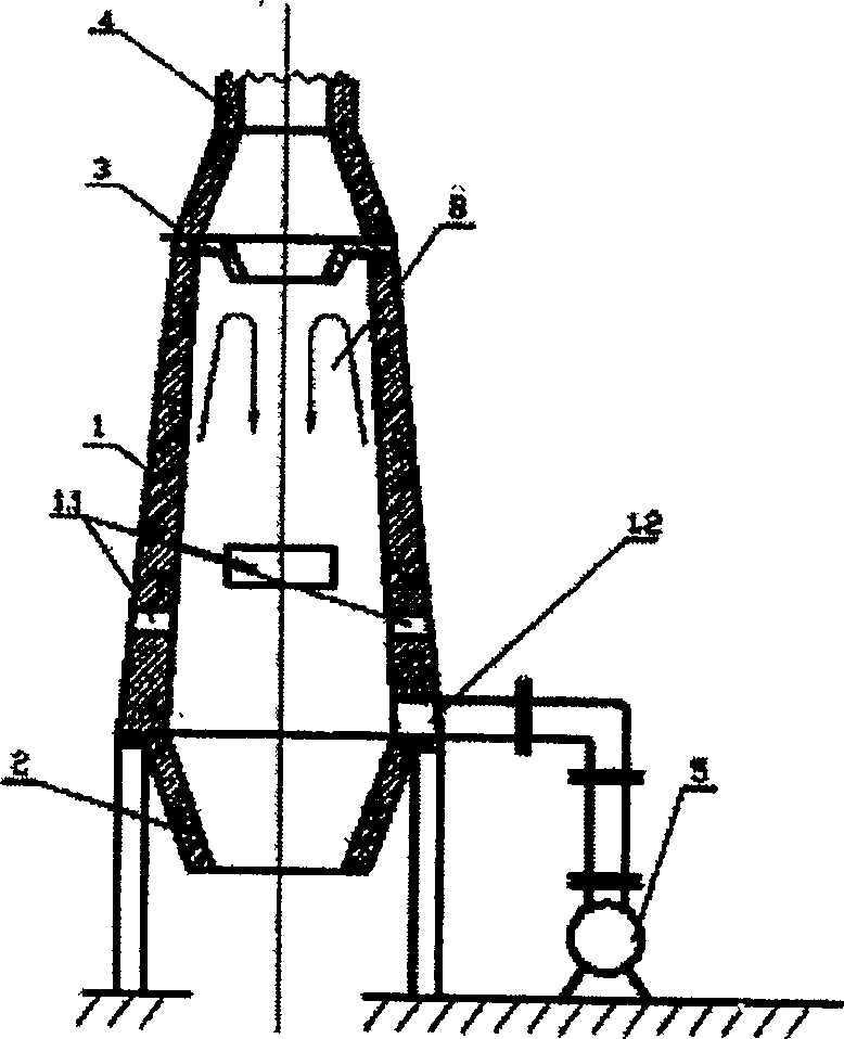
[0022] In order to better understand the present invention, the present invention will be further described below in conjunction with the accompanying drawings.

[0023] Such as figure 1 As shown, the coal-water slurry fuel clean hot air furnace of the present invention contains a body of furnace, and the body of furnace mainly includes a conical hearth 1, a dust deflector 3, a furnace cover 4, an ash hopper 2 and a blower 5, and the lower end of the conical hearth 1 There are several coal-water slurry nozzles 1.1, and the present invention also includes an ash settler 7; the lowermost end of the conical furnace 1 is connected to the ash collecting hopper 2, the uppermost end is connected to the dust deflector 3, and the top of the dust deflector 3 is connected to the furnace cover 4 , the furnace cover 4 is connected with the ash settler 7 through the hot air pipe 6; the blower 5 is connected with the conical furnace 1 through the conical furnace 1 through the secondary nozzl...


PUM


Abstract

The invention discloses coal water slurry fuel cleaning warm air furnace. It includes furnace body. The furnace body includes furnace chamber, dust guide plate, furnace mantle, dust collecting bucket, and air blower. The bottom end of the furnace chamber has many coal water slurry jets. The invention also has ash settler. The furnace chamber is cone. And its bottom end is connected to ash collecting bucket. Its top end is connected to ash guide plate. The ash guide plate is connected to the furnace mantle. It is connected to the ash setter. The air blower is connected to the cone furnace chamber. Because of adopting cone furnace body, ash guide plate, and ash setter, the invention can make the fuel burn more completely, dust much less. And its reliability is high. It can be used in the place which needs cleaning warm air.

Description

technical field [0001] The invention belongs to the field of air furnaces, in particular to a coal-water slurry fuel clean hot air furnace. Background technique [0002] At present, the ceramic industry and many other industries use spray drying towers, which use hot air to dry materials at high temperatures. The spray drying method has a large output and high fuel consumption, so it is an important direction to adopt lower-priced fuel. There are many fuels that can be used for spray drying, such as diesel, heavy oil, coal water slurry, etc. Due to the rapid rise of fuel prices in recent years, some previously neglected fuels such as coal-water slurry have been used in large quantities, especially in the drying of ceramic slurry. The price of coal-water slurry is low, and it is basically the same as heavy oil. method. But the coal water slurry itself also has some inherent defects. It has a large residual ash, so the coal water slurry furnace is easy to slagging on the fur...

Claims


Application Information

Patent Timeline
Patent Type & Authority Patents(China)
IPC IPC(8): F23C3/00F23J15/00
Inventor 李新衡谢平波王燕民
Owner SOUTH CHINA UNIV OF TECH
Why Eureka
Try Eureka