Yarn resistant twisting head

A technology of twist resistance and yarn, which is applied in the field of yarn resistance head, can solve the problems of constant change, cost, complexity, etc., and achieve the effect of good spinning effect, reduced complexity and high spinning stability

Inactive Publication Date: 2009-05-20
SAURER GERMANY GMBH & CO KG
View PDF11 Cites 0 Cited by
  • Summary
  • Abstract
  • Description
  • Claims
  • Application Information

AI Technical Summary

Problems solved by technology

[0033] That is to say, in order to produce the helical structure on the inlet region of the yarn navel, a relatively complex and overall particularly expensive tool is required
[0034] A further disadvantage in these yarn navels is that the helical structure flows out towards the edge of the yarn navel, which results in the yarn formation areas in the grooves of the spinning The distance between the helical structures of the true twist of the thread is constantly changing.

Method used


Image

  • Yarn resistant twisting head
  • Yarn resistant twisting head
  • Yarn resistant twisting head

Examples


Embodiment Construction

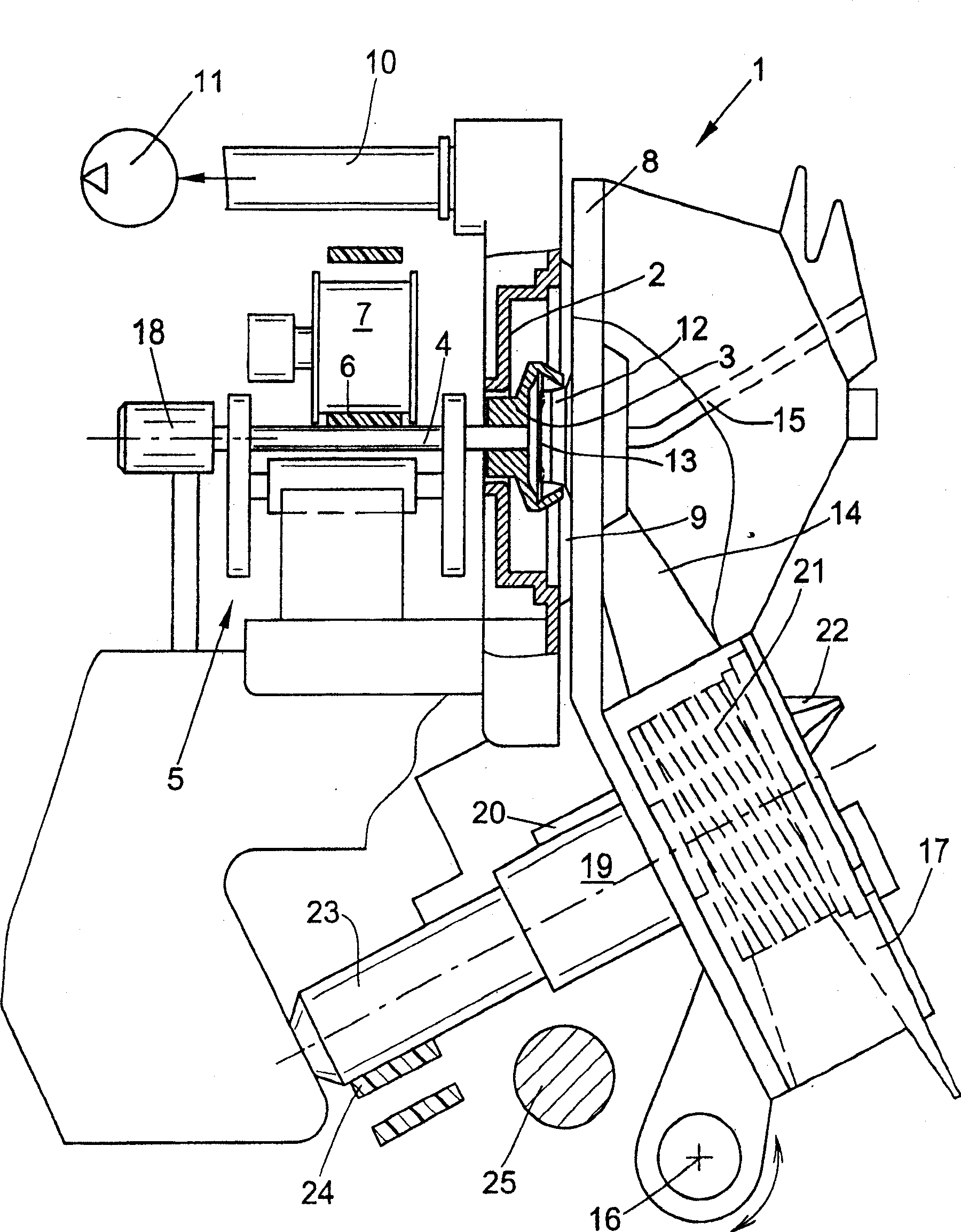
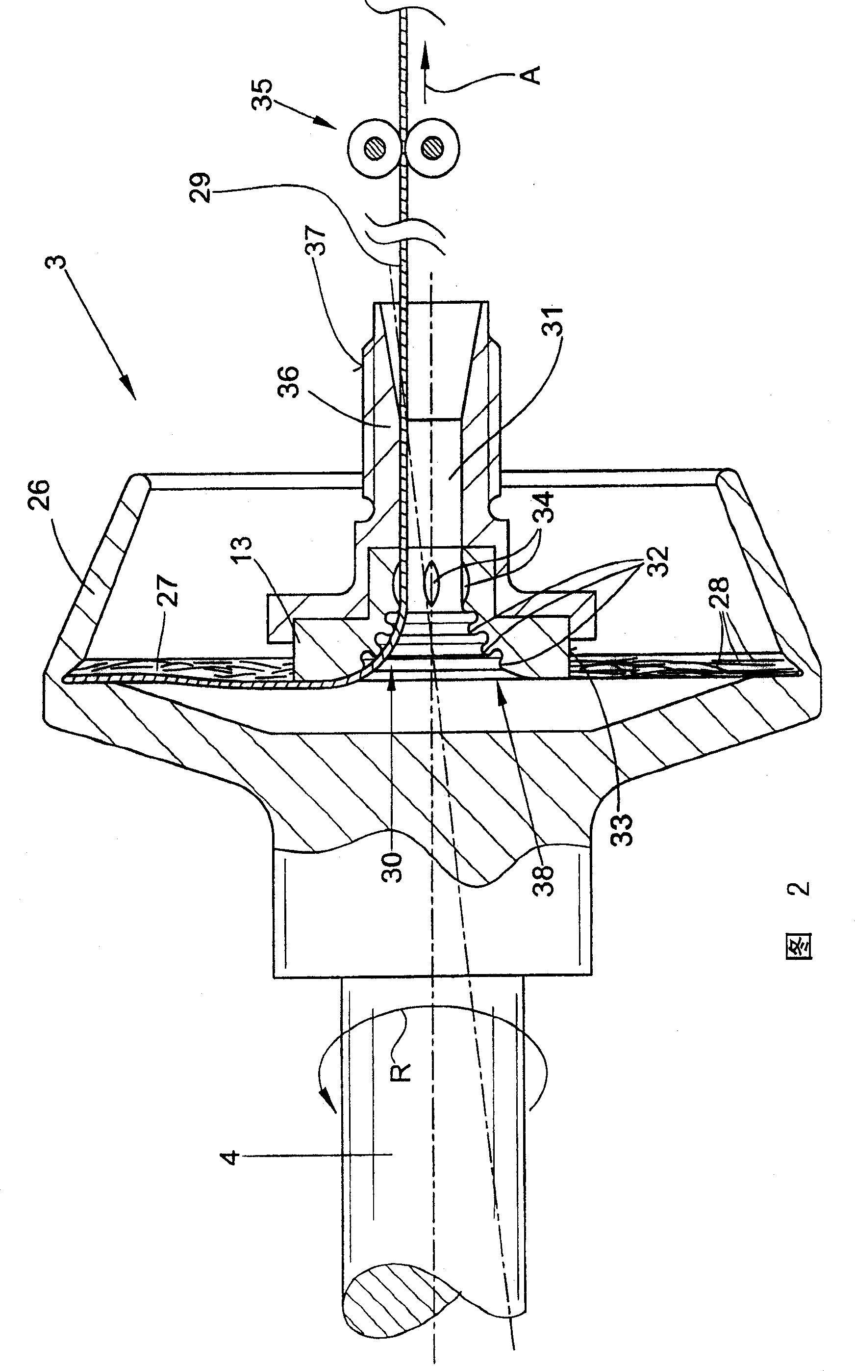
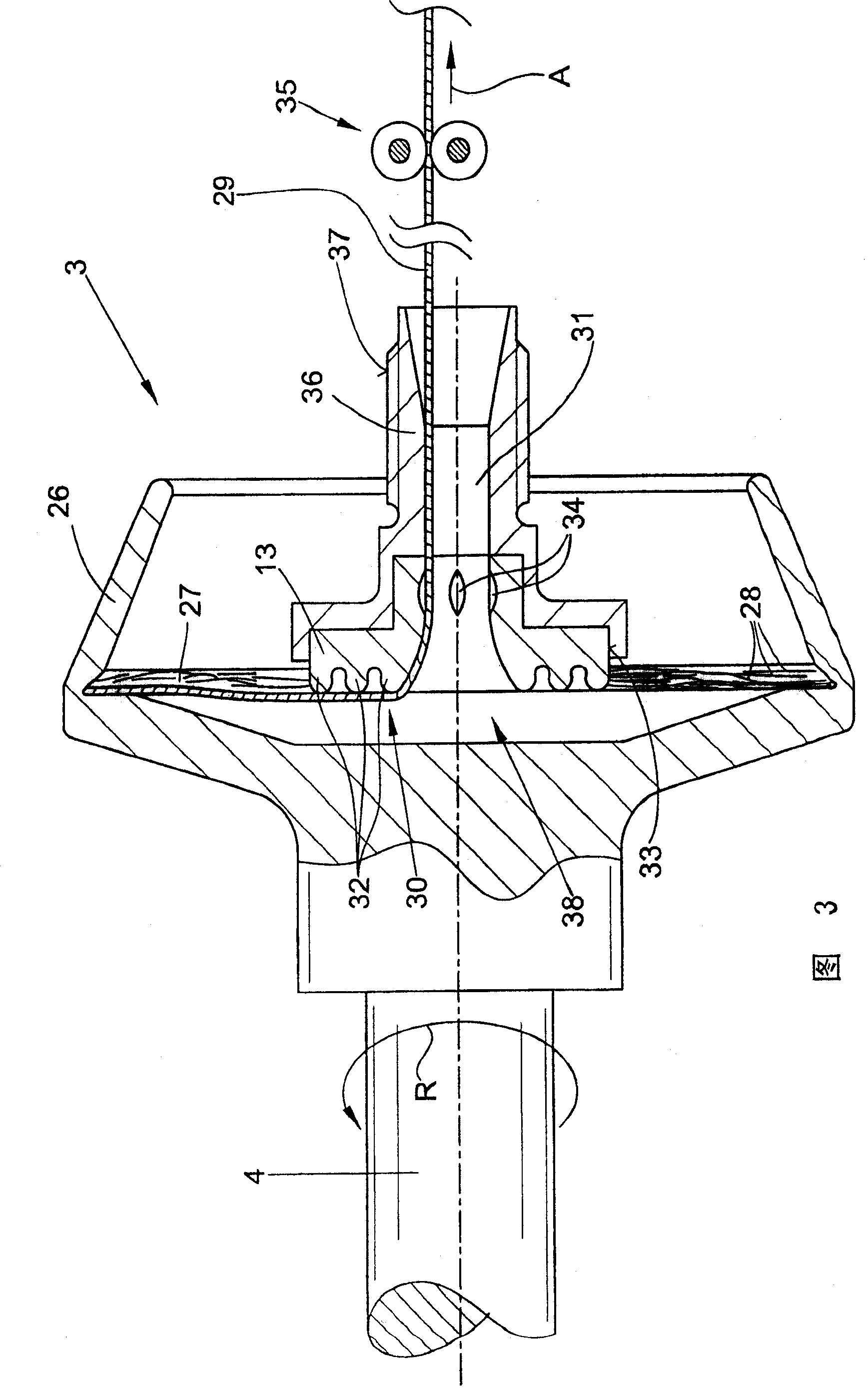
[0061] exist figure 1 The air spinning device shown schematically in , is designated as a whole by the reference number 1 . Such a spinning device has, as is known, a rotor housing 2 in which the rotor part of a rotor 3 rotates at a relatively high rotational speed.

[0062] The rotor 3 is supported with its rotor shaft 4 in the bearing wedge of a washer bearing 5 and is driven by a machine-length tangential drive belt 6 which is loaded by means of a pressure roller 7 . The axial fixation of the rotor shaft 4 takes place, for example, via a permanent-magnetic thrust bearing 18 .

[0063] The rotor housing 2 which is open towards the front can be closed during spinning by a pivotably mounted cover element 8 .

[0064] That is to say, a channel disk opens into the cover element, which channel disk bears against the rotor housing 2 with a lip seal 9 .

[0065] Furthermore, the rotor housing 2 is connected via a corresponding suction duct 10 to a low-pressure source 11, which g...


PUM


Abstract

The invention relates to a yarn navel of an air spinning device, which has a coaxial structure arranged in an inlet funnel, and grooves arranged at a distance, which are positioned at the downstream of the coaxial structure. According to the invention, the coaxially arranged structures ( 30 ) are formed by circular protrusions or grooves ( 32 ) of different diameters.

Description

technical field [0001] The invention relates to a yarn navel for an air spinning device. Background technique [0002] Yarn navels for open-end spinning devices have long been known in the art and are known in various embodiments. [0003] A common problem in open-end spinning devices is that the true twist of the yarn introduced by the rotation of the spinning cup is unevenly incorporated into the yarn being formed. [0004] That is to say, the true twist of the yarn is firmly deposited on the yarn section that is then located between the yarn navel and the yarn draw-off mechanism of the rotor spinning device. [0005] In contrast to this, the true yarn twist is often introduced only particularly incompletely into the yarn section preceding the yarn navel. [0006] Since a particularly low yarn twist in the yarn section located between the rotor groove and the yarn navel has a particularly bad influence on the spinning stability of the rotor spinning device, it has previo...

Claims


Application Information

Patent Timeline
Patent Type & Authority Patents(China)
IPC IPC(8): D01H4/10D01H4/40
Inventor T·维德B·施勒默
Owner SAURER GERMANY GMBH & CO KG
Why Eureka
Try Eureka