
Universal rotation hinge

A kind of rotating hinge, all-purpose technology, applied in the direction of furniture connection, connecting components, stools, etc., can solve the problem of noise, etc., to achieve the effect of large rotation angle range, stable rotation, no noise support strength

Active Publication Date: 2009-05-06
LEGGETT & PLATT JIAXING +1
View PDF6 Cites 4 Cited by
  • Summary
  • Abstract
  • Description
  • Claims
  • Application Information

AI Technical Summary

Problems solved by technology

Therefore, the entire rotation angle of the hinge is limited to a certain extent, and a certain amount of noise will be generated when the locking pawl cooperates with the gear.

Method used

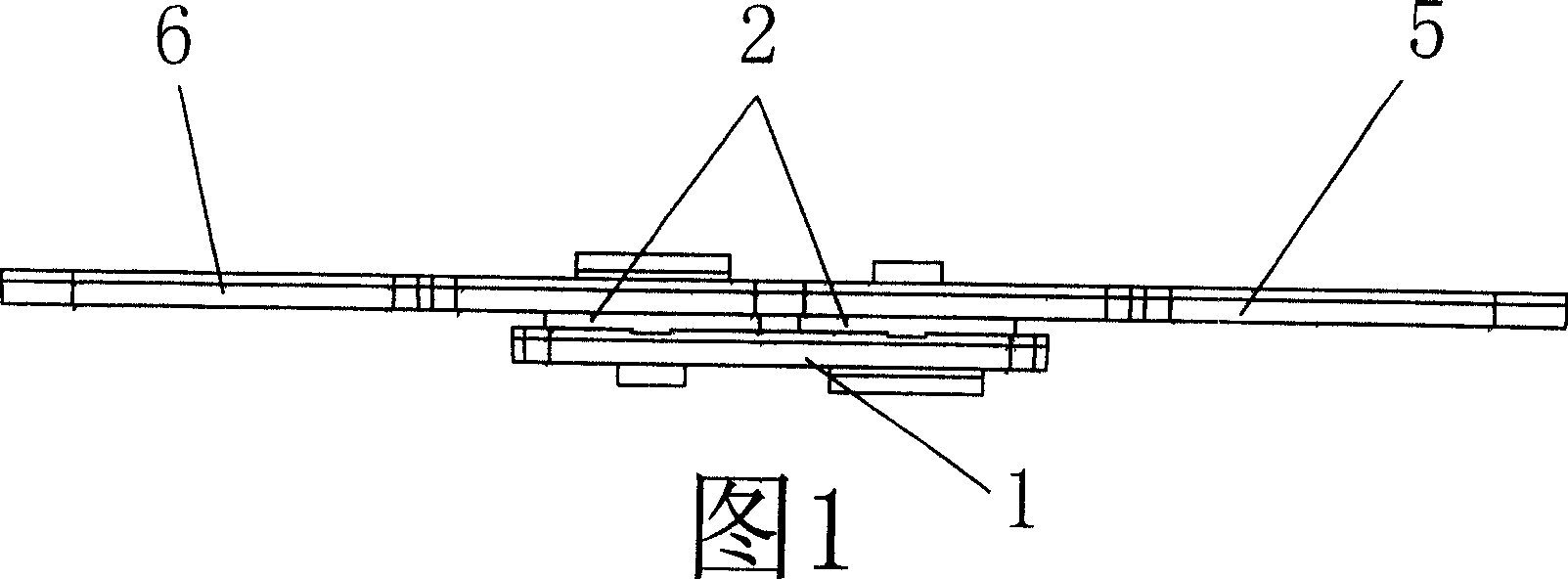
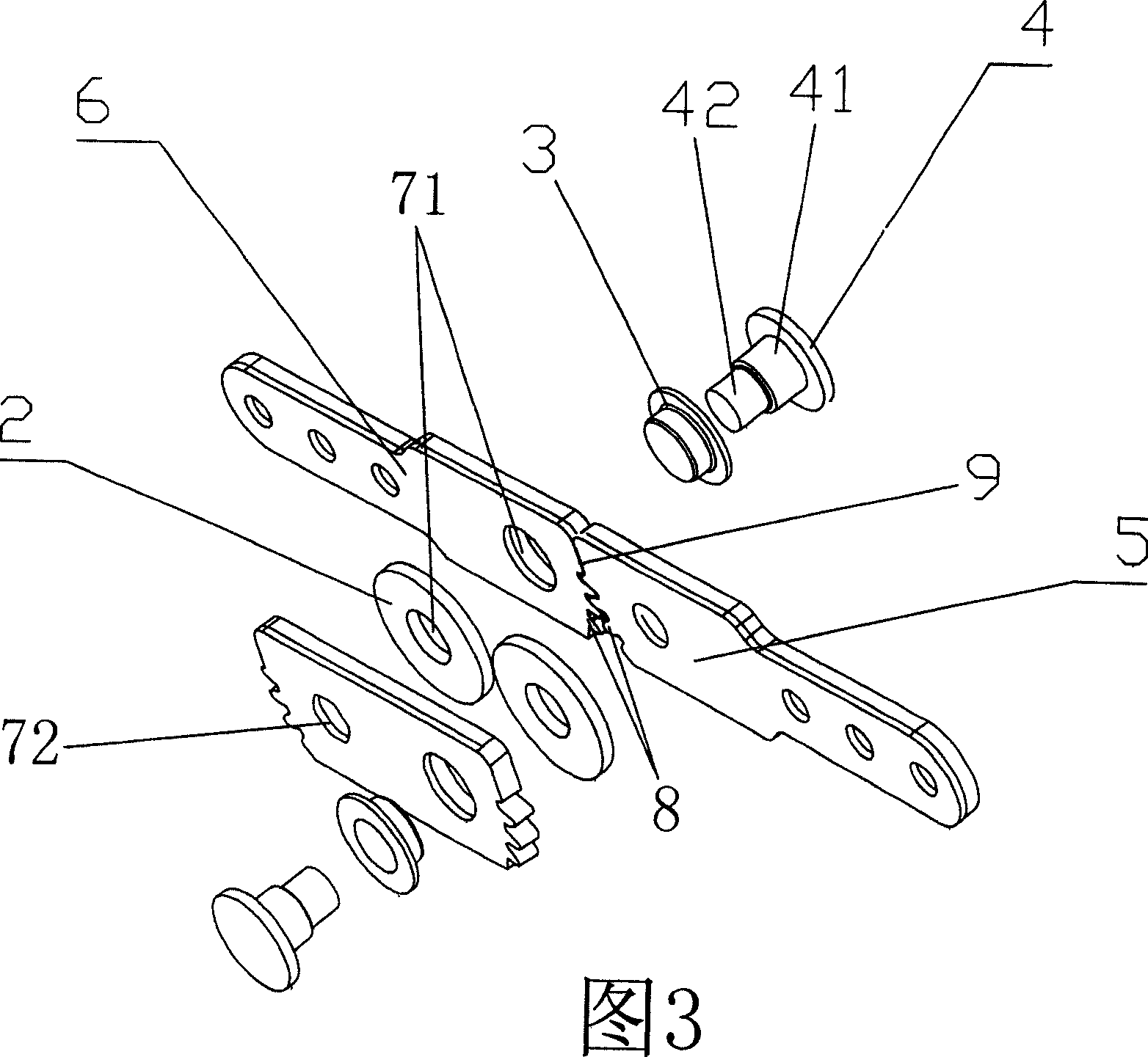

Image

  • Universal rotation hinge
  • Universal rotation hinge
  • Universal rotation hinge

Examples


Embodiment 1

[0021] see Figure 4 ~ Figure 6, the left connecting plate 6 and the right connecting plate 5 in Embodiment 1 are the same as the basic form, but the connecting device 1 adopts a first-level connecting device, including the upper toothed plate 10 of the first-level connecting device and the first-level connecting device The lower toothed plate 11, the upper toothed plate 10 of the first level connection device is the same as the lower toothed plate 11 of the first level connection device, and both ends are provided with supporting surfaces 9, The gear surface 8, the rotating shaft hole 71, the small rotating shaft hole 72, the upper toothed plate 10 of the first-stage connecting device and the lower toothed plate 11 of the first-stage connecting device are movably connected by the rotating shaft in the same manner as in Embodiment 1, and the first-stage connection The upper toothed plate 10 of the device is on the same plane and engaged with the left connecting plate 6, the lo...

Embodiment 2

[0023] see Figure 7 ~ Figure 9 , the left connecting plate 6 and the right connecting plate 5 in Embodiment 2 are identical to the basic form, but the connecting device 1 adopts a secondary connecting device, including the upper toothed plate 10 of the first connecting device, the lower tooth of the first connecting device Shaped plate 11, the upper toothed plate 12 of the second level connecting device, the lower toothed plate 13 of the second level connecting device, the upper toothed plate 10 of the first level connecting device, the lower toothed plate 11 of the first level connecting device, the second The upper toothed plate 12 of the stage connecting device and the lower toothed plate 13 of the second stage connecting device are the same, and both ends are provided with supporting surfaces 9, gear surfaces 8 and shaft holes 71 that match the left connecting plate 6 and the right connecting plate 5, The small shaft hole 72, the connection mode between the left connectin...


PUM


Abstract

The invention relates to an all-purpose turning joint which is a furniture member and comprises a right connecting plate and a left connecting plate, each of the two connecting plates is provided with a matching bearing surface and a gear surface at one end, the two connecting plates can enlarge the rotation angle through a plurality of steps of connecting device, each step of connecting device comprises an upper gear form plate and a lower gear form plate, the two ends of the upper gear form plate and the lower gear form plate are all provided with a bearing surface and a gear surface, the corresponding upper gear form plate and the lower gear form plate are movably connected through a rotation shaft; when the two connecting plates are stressed by the rotating force from the respective gear faces, the rotating force is stably transferred through the engaged gear surface and the limiting effect between the neighboring rotation shafts, and thus, the rotation angle between the two connecting plates is adjustable within the range of the gear face. Each rotation connecting point is all designed to the connection with the connecting plate, the connecting device, a liner bushing, an elastic gasket through the rotation shaft, and thus, the rotation position of a hinge can stop at any angle. Compared with the existing art, the invention has the advantages that the range of the rotation angle is large, the rotation position can stop at any angle, the rotation is stable, noise-free and the bearing strength is large, etc.

Description

Technical field: [0001] The invention relates to a furniture component, in particular to a universal rotating hinge for an adjustable backrest, armrest or headrest of sitting or lying furniture. Background technique: [0002] The hinges currently used on furniture are usually installed between a support cam and a pressing boss by means of external gears, so that the entire effective range that works with the locking pawl is limited by the support cam on one side and the other side by the support cam. Restricted by the hold-down boss. Therefore, the entire rotation angle of the hinge is limited to a certain extent, and certain noises will be generated during the mating process of the locking pawl and the gear. Invention content: [0003] The technical problem to be solved by the present invention is to provide a universal rotary hinge with arbitrarily adjustable rotation angle, stable rotation, no noise and certain supporting force. [0004] The technical solution adopted...

Claims


Application Information

Patent Timeline
Patent Type & Authority Patents(China)
IPC IPC(8): F16B12/00A47C7/00
Inventor 黄金泉迈克尔·马克特
Owner LEGGETT & PLATT JIAXING
Learn More