Method and device for track counting in optical recording media

An optical recording medium, technology of recording medium, applied to optical recording carrier, optical recording/reproduction/erasing method, recording/reproduction with optical method, etc., can solve the problem of direction determination, etc. problem, to achieve the effect of simple and light mechanical structure, reliable identification, and suppression of interference DC offset

Inactive Publication Date: 2009-04-22
THOMSON LICENSING SA
View PDF6 Cites 0 Cited by
  • Summary
  • Abstract
  • Description
  • Claims
  • Application Information

AI Technical Summary

Problems solved by technology

However, in the case of "-R" or "-RW" type write-once or write-multiple optical storage media, there may be cases that have not yet been written and scanning it will neither generate a data signal nor cause an Different reflective areas between grooves and lands
Therefore, in the area that has not been written, the above-mentioned method of generating the mirror zero-crossing signal, and the direction determination based on this method cannot be applied

Method used


Image

  • Method and device for track counting in optical recording media
  • Method and device for track counting in optical recording media
  • Method and device for track counting in optical recording media

Examples


Embodiment Construction

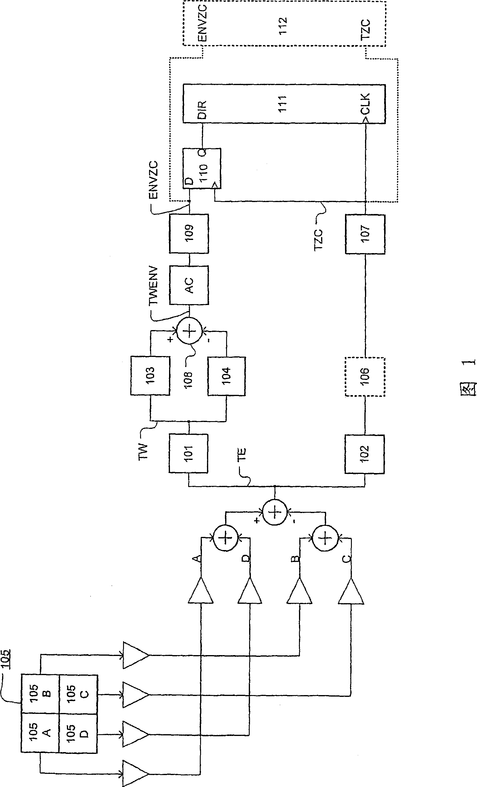
[0048] FIG. 1 shows the acquisition of the wobble signal TW by evaluating the high-frequency components of the track error signal TE. As for the track error signal TE, it is generally formed by combining the output signals of the photodetectors in such a way that the signal of the left half of the detector and the signal of the right half of the detector are subtracted from each other. Additionally, in order to be able to form an astigmatic focus error signal, the photodetector 105 is shown here to contain four photosensitive regions 105A, 105B, 105C, and 105D. A photodetector with only two photosensitive areas divided into left and right halves is sufficient to obtain the wobble signal TW. In the case of the four-region photodetector 105 depicted in Figure 1, this is accomplished by summing the signals corresponding to regions 105A and 105D, and 105B and 105C.

[0049] The resulting frequency of the wobble signal TW obtained from the wobble track should have a value at a suf...


PUM


Abstract

The invention relates to the identification of the direction of the relative movement between a scanning beam of an optical scanner and the tracks of optical storage media. Use is made of the fact that the amplitude of the component TW of a track error signal TE, said component being brought about by wobble of the tracks, is maximal in the track center and minimal in the region between the tracks. A signal TW is thus present which does not assume its maxima and minima across the scanning location x at the same places as the track error signal TE. The invention describes devices and methods for determining the movement direction DIR of the scanning beam from the phase shift between the two signals.

Description

technical field [0001] The invention relates to the control of a device for accessing an optical storage medium, and more particularly to the identification of the direction of relative movement between a scanning beam of an optical scanner and a track of an optical storage medium. Background technique [0002] On pre-recorded optical storage media, i.e. so called ROM (Read Only Memory) media like CD-ROM (Compact Disc Read Only Memory), DVD-ROM (Digital Versatile Disc Read Only Memory) or their future successors, Or on already pre-recorded media, i.e. so-called R / On RW (recordable / rewritable) media, the relative motion direction between the spot of the scanning beam and the track of the media can be detected by the estimation of the track error signal, and the envelope of the data signal. For this purpose, the track zero-crossing signal is formed by a comparator, and the zero-crossing signal is mirrored. According to FIG. 6, the track zero crossing signal TZC is generated...

Claims


Application Information

Patent Timeline
Patent Type & Authority Patents(China)
IPC IPC(8): G11B7/085G11B7/005G11B7/007
CPCG11B7/08541G11B7/0053G11B7/24082G11B7/085G11B7/007G11B7/09G11B7/005
Inventor 克里斯琴·比克勒
Owner THOMSON LICENSING SA
Why Eureka
Try Eureka