
Closed square cell

A technology for square batteries and battery casings, which is applied to battery pack components, battery covers/end covers, battery boxes/coatings, etc., and can solve problems such as uneven working pressure of cracking bends and low reliability of cracking bends , to achieve the effect of stable working pressure, high crack resistance and reduced deviation

Inactive Publication Date: 2009-04-08
HITACHI MAXELL ENERGY LTD
View PDF7 Cites 0 Cited by
  • Summary
  • Abstract
  • Description
  • Claims
  • Application Information

AI Technical Summary

Problems solved by technology

Therefore, the working pressure of the cracking bends of each battery is uneven, and there is a problem of low reliability of the cracking bends

Method used


Image

  • Closed square cell
  • Closed square cell
  • Closed square cell

Examples


Embodiment 1

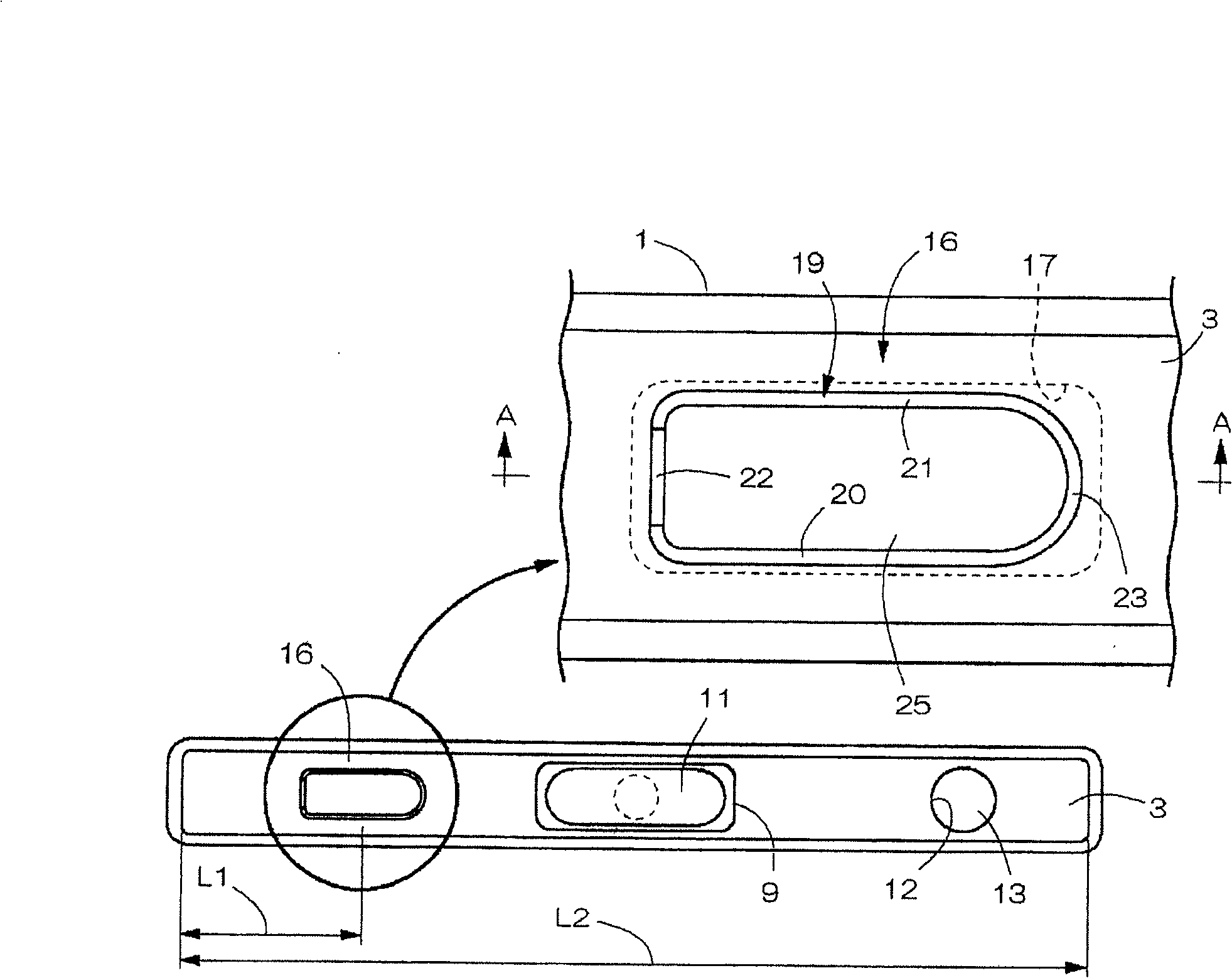
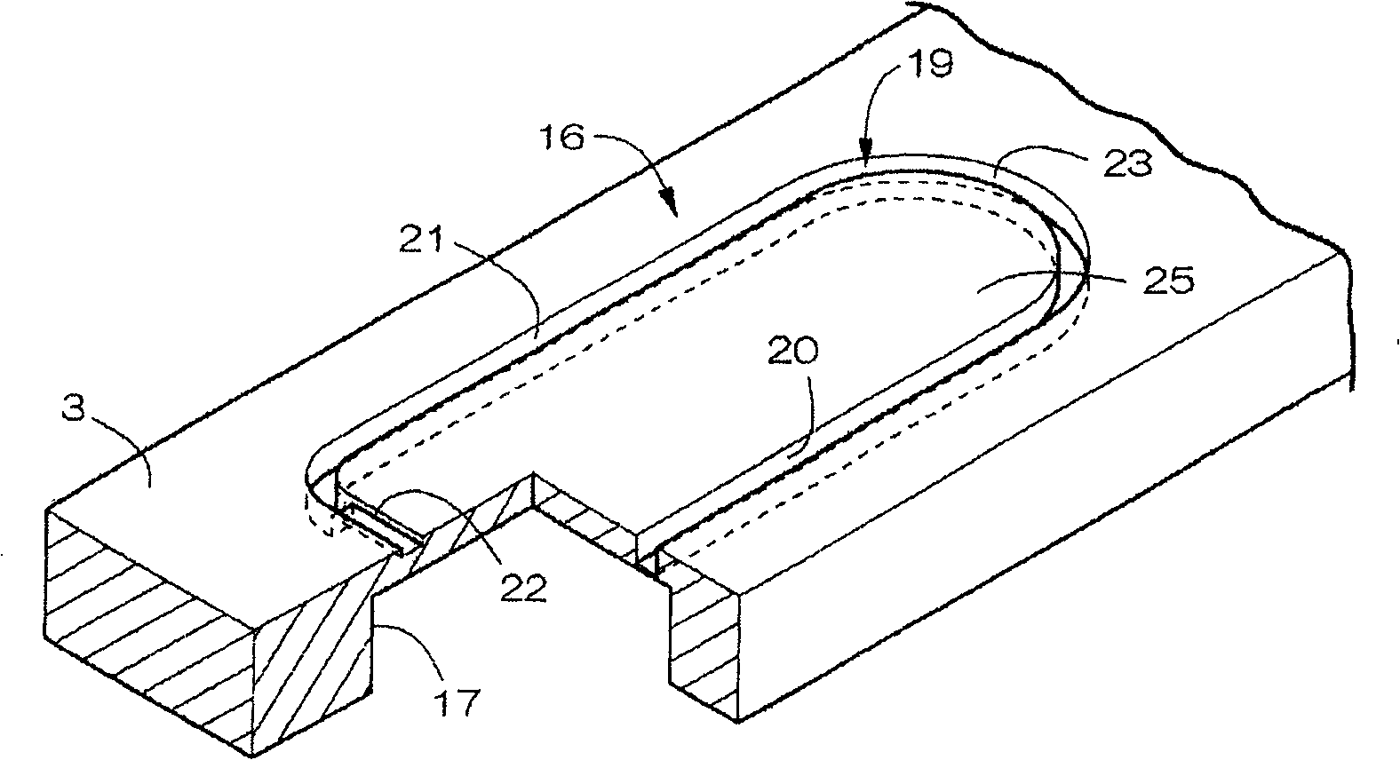
[0029] Figure 1 to Figure 4 Example 1 showing a lithium ion secondary battery as a sealed prismatic battery of the present invention, such as Figure 4 As shown, it is equipped with: a bottomed square battery case 1 with long left and right lateral openings on the top, an electrode body 2 and a non-aqueous electrolyte contained in the battery case 1, and the top of the opening of the battery case 1 is closed. The horizontally long cover 3, the plastic insulator 5 disposed inside the cover 3, and the like. The battery case 1 is formed by deep-drawing a plate made of aluminum or aluminum alloy to make a thin piece with vertically long top and bottom.

[0030] In the electrode body 2 , a separator made of a polyethylene microporous film is interposed between a sheet-shaped positive electrode and a negative electrode and wound in a spiral shape. A thin plate-shaped positive electrode current collector lead 6 made of aluminum or an aluminum alloy is drawn upward from the positiv...

Embodiment 2

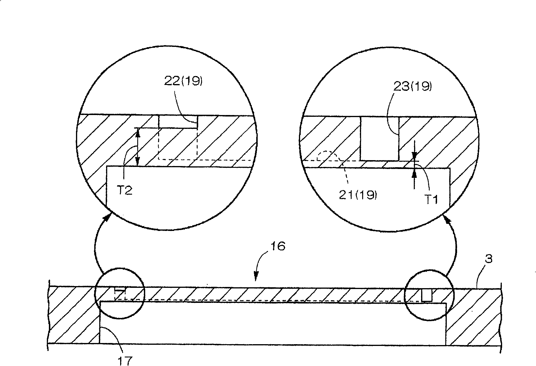
[0043] In Example 2, each bottom wall thickness T1 of the grooves 20 , 21 , and 23 other than the end side groove 22 of the cleavage bend 16 is set to 0.031 mm. Since the other points are the same as those in Embodiment 1, description thereof will be omitted.

Embodiment 3

[0045] In Example 3, the front and rear thickness of the battery is increased to 4.0 mm, and correspondingly, the front and rear width of the cracking bend 16 is also increased to 2.5 mm. The respective bottom wall thickness dimensions T1 of the groove portions 20 , 21 , and 23 other than the end side groove portion 22 are set to 0.035 mm, respectively. Other points are the same as in Example 1.


PUM


Abstract

A sealed prismatic battery includes a laterally elongated cap that closes the upper surface of the opening of a battery can 1 and a safety vent that is provided at the cap and opens when the battery internal pressure abnormally rises. The safety vent has a looped groove that is formed recessed and located nearer to the left end of the cap on the outer surface side of the cap. The looped groove is annularly formed of front, rear, left and right groove portions into a laterally elongated prismatic shape, and the thickness of the bottom wall of the end side groove portion is thicker than that of the bottom walls of the other groove portions. The center side groove portion of the looped groove is formed into a circular arc shape curved convex toward the center side of the cap.

Description

technical field [0001] The present invention relates to a sealed prismatic battery equipped with a cracking bent that cracks when the internal pressure of the battery rises abnormally. Background technique [0002] If an excessive electrical load or excessive thermal load is applied to the above-mentioned sealed prismatic battery, a short circuit occurs inside the battery, gas is generated, and the internal pressure of the battery abnormally rises. When the battery is overcharged, gas will be generated inside the battery due to the decomposition of the electrolyte, and the internal pressure of the battery will rise abnormally. If the battery cannot withstand the abnormal rise in internal pressure and ruptures, its internal substances will be splashed out. Therefore, the battery is equipped with a cracking bend to prevent battery rupture, so that when the internal pressure exceeds a predetermined value, a crack occurs to release the internal pressure of the battery. [0003...

Claims


Application Information

Patent Timeline
Patent Type & Authority Patents(China)
IPC IPC(8): H01M2/12H01M50/103H01M50/176H01M50/553H01M50/627
CPCH01M2/30Y02E60/12H01M2/1241H01M2/0207H01M2/361H01M2/06Y02E60/10H01M50/3425H01M50/553H01M50/103H01M50/176H01M50/627H01M50/30H01M50/147H01M50/20
Inventor 松本佳巳渡边修杣友良树
Owner HITACHI MAXELL ENERGY LTD
Learn More