
Communication network, communication controller, bus monitor and method for controlling the communication network

A communication controller, communication network technology, applied in the direction of bus network, ring network, data exchange network, etc., can solve the problems of reducing efficiency, increasing cost, restricting system design, etc.

Inactive Publication Date: 2009-03-18
NXP BV
View PDF2 Cites 0 Cited by
  • Summary
  • Abstract
  • Description
  • Claims
  • Application Information

AI Technical Summary

Problems solved by technology

Of course, providing the bus guardian with its own clock not only incurs an increase in cost, but also limits the design of the system and reduces efficiency, since the "interframe space" must be sized such that the time slots caused by clock frequency deviations overlap even won't happen for many years

Method used


Image

  • Communication network, communication controller, bus monitor and method for controlling the communication network
  • Communication network, communication controller, bus monitor and method for controlling the communication network
  • Communication network, communication controller, bus monitor and method for controlling the communication network

Examples


Embodiment Construction

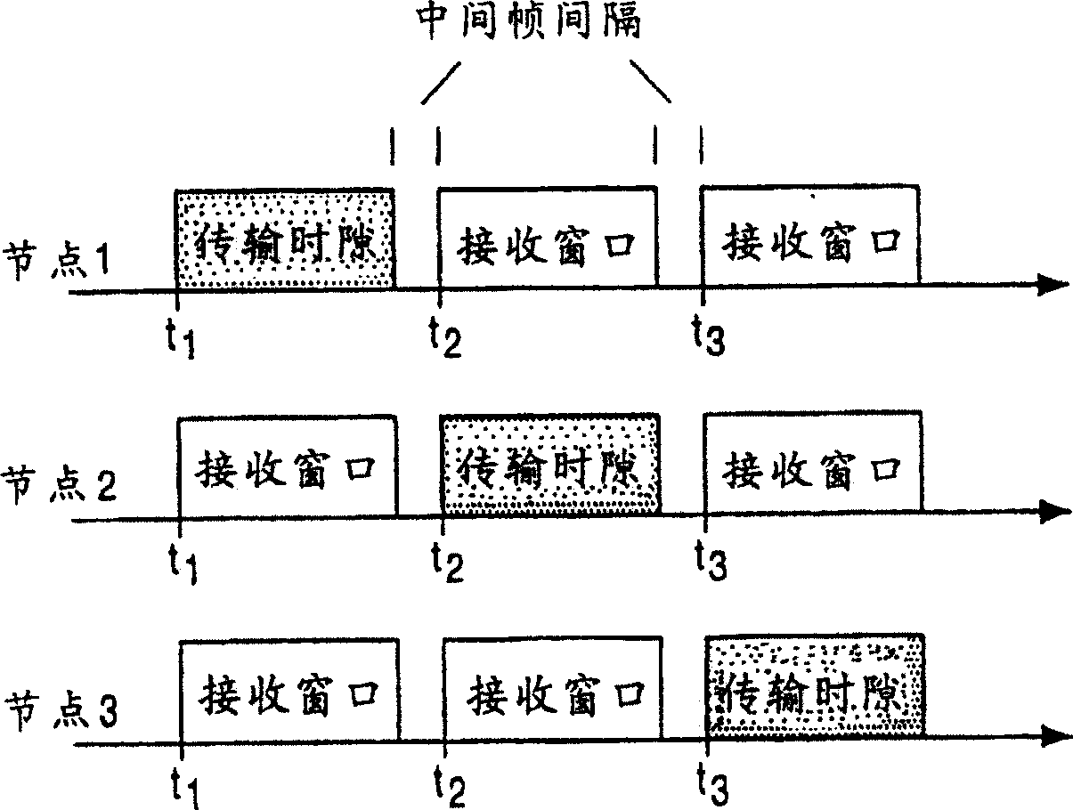
[0032] attached figure 1 A simplified communication schedule of a communication network with three network nodes 1, 2 and 3 is shown, wherein said three network nodes may only transmit data at set times t1, t2 and t3.

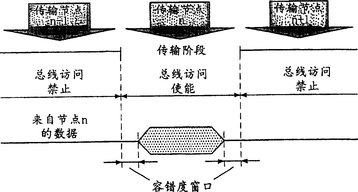
[0033] attached figure 2 Shows the relationship between the communication schedule in a communication controller and the monitoring schedule of an associated bus guardian. The bottom row shows the time interval for node n, which is assigned to node n according to the communication schedule. It shows the allowed time of the bus guardian. Bus guardians are enabled at one point and disabled at a later point, each offset by a tolerance window.

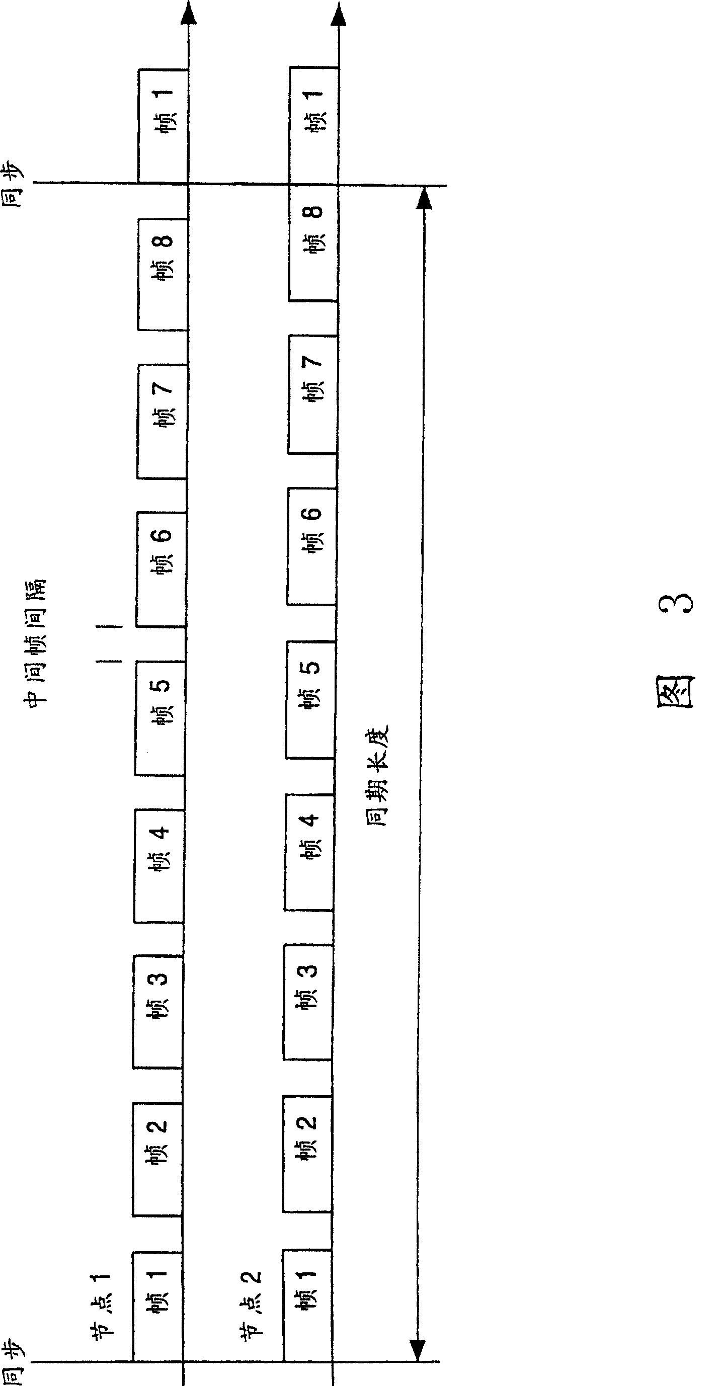
[0034] Figure 3 shows a simplified time multiplexing scheme with two communication nodes and a communication cycle consisting of 8 data packets (frames). This example shows that the transmission times of the two nodes may be offset in such a way that there is a risk of a collision at the end of the communication cycle ...


PUM


Abstract

The arrangement has at least 2 nodes provided with communications schedule time slices for access to a transmission medium. Each node has at least one communications controlerss with a first scheduler for controlling access according to the schedule; the network has at least one bus monitor with a second scheduler for monitoring access to the medium by nodes according to a monitoring schedule. A global clock signal is used to control both schedulers. The arrangement has at least two nodes between which data are transferred over a transmission medium and that are provided with time slices for access to the medium in a communications schedule. Each node has at least one communications controlers with a first scheduler for controlling access in accordance with the schedule and the network has at least one bus monitor with a second scheduler for monitoring access to the medium by nodes in accordance with a monitoring schedule. A global clock signal is used to control both schedulers. AN Independent claim is also included for a method of controlling an inventive arrangement.

Description

technical field [0001] The present invention relates to a communication network and a method of controlling a communication network, such a communication network can be obtained from, for example TTP: "derive by wire" in greifbarer nahe', Dr. stefan polenda, Georg Kroiss; "Elektronik", N.14 1999 pages36 -43 learned. Background technique [0002] For distributed real-time computer systems, such as those used in the automotive industry, time-triggered communication protocols such as TTP or FlexRay have generally been used. The media access protocol is based on a static communication schedule that is predetermined during system design. In this schedule, it is decided when each communication node can send data in a communication cycle. [0003] Because of the tolerance of the local clock source, slight deviations may occur for the communication schedules of the individual nodes from each other. So that overlapping cannot occur despite these deviations, a gap ("interframe gap"...

Claims


Application Information

Patent Timeline
Patent Type & Authority Patents(China)
IPC IPC(8): H04L12/28H04L12/24H04L12/26H04J3/16H04J3/06H04L5/14H04L7/00H04L12/403H04L12/42H04L12/44H04L12/56
CPCH05K999/99H04L12/40026H04L12/422H04L12/40013H04J3/0694H04L5/1484H04L12/44H04J3/0652H04L12/40
Inventor P·福尔曼M·青克
Owner NXP BV
Learn More