A chip washing device
A washing device and chip technology, which is applied to transmission devices, cleaning flexible items, and cleaning methods using liquids, etc., can solve the problem of uneven flow rate of washing liquid, etc., and achieve simple transmission devices, increased consistency, and good repeatability. Effect
- Summary
- Abstract
- Description
- Claims
- Application Information
AI Technical Summary
Problems solved by technology
Method used
Image
Examples
Embodiment 1
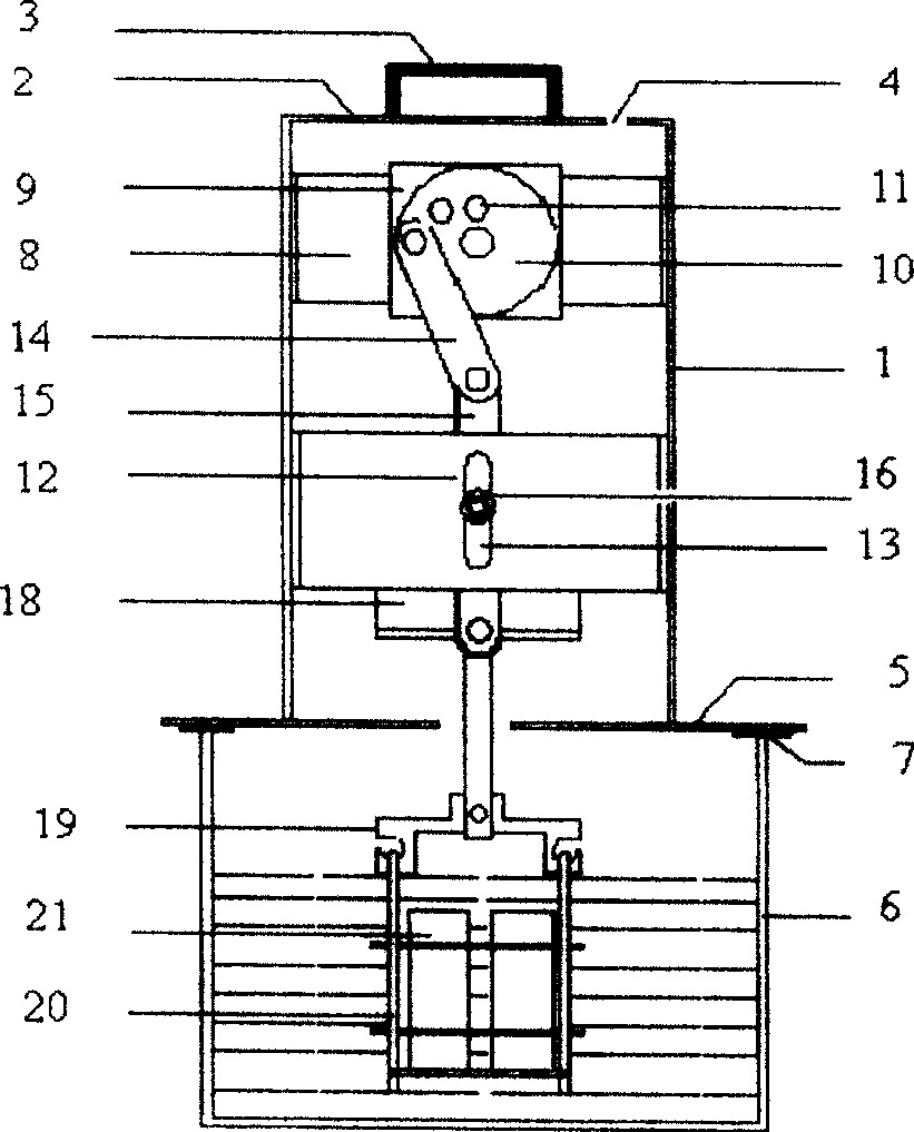
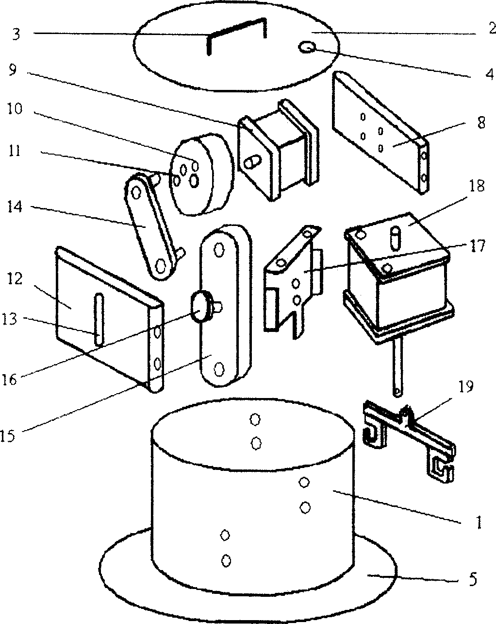
[0026] Such as figure 1 , figure 2 As shown, the present invention includes an outer cylinder 1, and an upper cover 2 is arranged on the top of the outer cylinder 1. The top of the upper cover 2 has a handle 3 for easy lifting, and the upper cover 2 is also provided with a small hole 4 through which the power cord can pass through. enter. The bottom of the outer cylinder 1 is connected to a bottom plate 5 by bonding or screwing, the bottom plate 5 together with the outer cylinder 1 can sit on a chip washing container 6 (such as a beaker), and a circle of elastic pads 7 for buffering can be arranged at the bottom of the bottom plate 5 . The outer cylinder 1 is connected to a motor fixing plate 8 by bonding or screwing, the motor 9 is connected to the fixing plate 8, the output end of the motor 9 is fixedly connected to the center of a runner 10, and several distances are arranged eccentrically on the runner 10. Eccentric holes 11 with different center distances. A slideway...
Embodiment 2
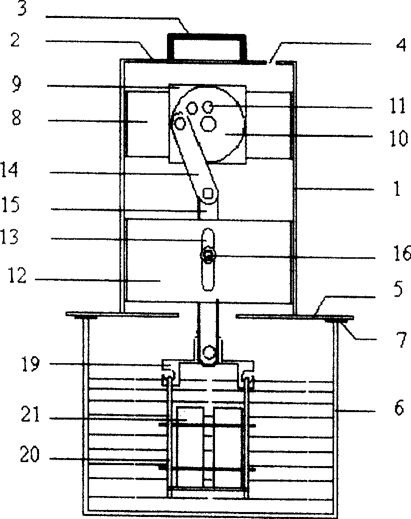
[0028] Such as image 3 As shown, the difference between the present embodiment and the first embodiment is that the bottom of the sliding rod 15 is directly connected to the hook 19, and the second motor 18 is not provided, so that the chip 21 only reciprocates up and down under the drive of the sliding rod 15, without rotational movement.
Embodiment 3
[0030] Such as Figure 4 As shown, the difference between this embodiment and Embodiment 1 is: a long rod 22 is fixedly connected to the output end of the motor 9, and a row of through holes 23 are provided on the long rod 22, and the output end of the motor 9 can be adjusted according to the needs of the vibration amplitude. Fixing in any one of the through holes 23, and then pivotally connecting the crank rod 14 in any other of the through holes 23, this structure can provide more amplitude changes.
PUM
 Abstract
Description
Claims
Application Information
 - R&D
- Intellectual Property
- Life Sciences
- Materials
- Tech Scout
- Unparalleled Data Quality
- Higher Quality Content
- 60% Fewer Hallucinations
Browse by: Latest US Patents, China's latest patents, Technical Efficacy Thesaurus, Application Domain, Technology Topic, Popular Technical Reports.
© 2025 PatSnap. All rights reserved.Legal|Privacy policy|Modern Slavery Act Transparency Statement|Sitemap|About US| Contact US: help@patsnap.com


