Excitation of switch magnetic resistance motor

A technology of reluctance motor and excitation motor, which is used in AC motor control, electronic commutation motor control, single motor speed/torque control and other directions, and can solve problems such as being unsuitable for driving devices

Inactive Publication Date: 2009-01-21
NIDEC SR DRIVES
View PDF3 Cites 0 Cited by
  • Summary
  • Abstract
  • Description
  • Claims
  • Application Information

AI Technical Summary

Problems solved by technology

Because of the peak current requirements, these systems are not suitable for use with drives in which two phases are conducted simultaneously

Method used


Image

  • Excitation of switch magnetic resistance motor
  • Excitation of switch magnetic resistance motor
  • Excitation of switch magnetic resistance motor

Examples


Embodiment Construction

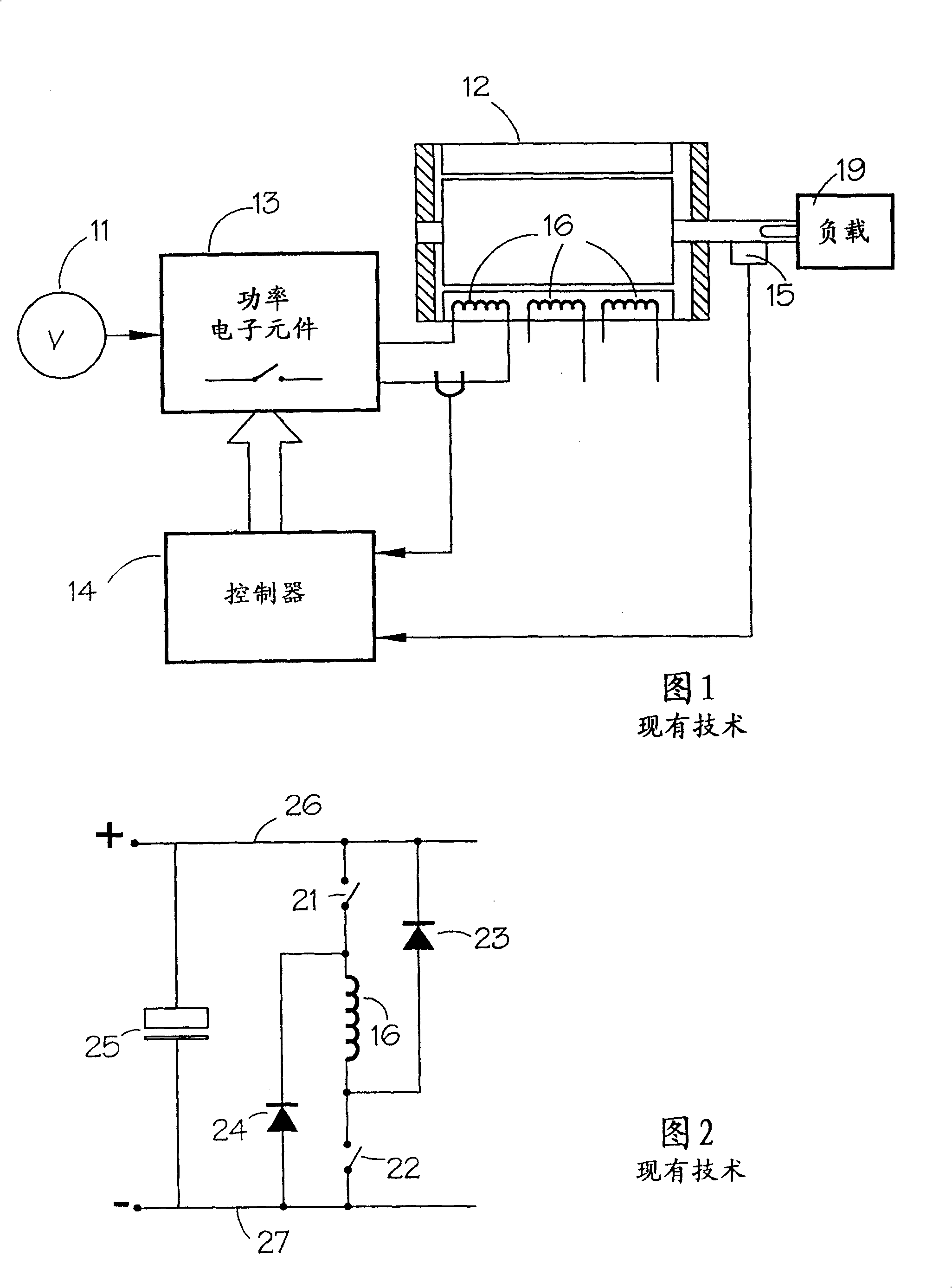
[0035] The present invention is implemented in a preferred embodiment in a transmission system such as that shown in FIG. 1 with a commutation circuit for each phase shown in FIG. 2 . According to the invention, by programming the controller 14, the control strategy is adapted to develop the idle configuration of the conversion circuit.

[0036] A typical rotor position sensor (rpt) of the three-phase four-pole drive of FIG. 1 is schematically shown in FIG. 6 . Three sensors are shown arranged mechanically offset by an angle of 120°, but any offset arrangement equal to an electrical angle of 120° may be used. This schematic has teeth with unit void ratio. In practice, this can be varied slightly to accommodate any non-ideal characteristics of the sensor, such as the beam width of an optical sensor or the fringing flux of a Hall effect sensor, so that the final signal of the rpt is at or acceptably close to a mark-to-space ratio of 1 .

[0037] The output of the rpt of Figur...


PUM


Abstract

The present invention relates to excitation of a switched reluctance motor in which a method of controlling a multi-phase switched reluctance motor by successively energizing the motor phases in sequence comprises the steps of: (i) energizing a phase of the motor; (ii) then energizing adjacent phases in sequence; and (iii) idling said one phase concurrently with energizing at least a portion of the adjacent phases in sequence, including initiating idling of said one phase and energization of an adjacent phase simultaneously, which Characterized by: (iv) repeating steps (ii) and (iii) in sequence for each successive pair of adjacent phases, addressing the technical problem of increasing the torque output of the motor without a subsequent increase in DC link current. The phases of the motor are controlled by a current chopping controller that employs an excitation strategy that minimizes the supply current generated for a particular output. This strategy allows the output phase to spin as long as it produces positive torque while the input phase is energized.

Description

technical field [0001] This invention relates to the excitation of switched reluctance motors. In particular, the invention relates to excitation that minimizes the supply current used for a particular output. Background technique [0002] The properties and operation of switched reluctance systems are well known in the prior art and are described, for example, in Stephenson and Blake, "Switched reluctance motors and their drives", PCIM'93, Nürnberg, June 21-24, 1993 characteristics, design, and applications", which is hereby incorporated by reference. FIG. 1 schematically shows a typical switched reluctance drive, where a switched reluctance motor 12 drives a load 19 . The input DC power source 11 may be a battery or a rectified and filtered AC mains. Under the control of the electronic control unit 14 , the DC voltage provided by the power source 11 is converted by the power converter 13 on the phase winding 16 of the motor 12 . For proper operation of the drive, this ...

Claims


Application Information

Patent Timeline
Patent Type & Authority Patents(China)
IPC IPC(8): H02P6/00H02P6/08H02P25/08
CPCH02P25/085H02P25/092H02P25/08
Inventor 查尔斯·R·埃略特伊恩·乔迪森
Owner NIDEC SR DRIVES
Why Eureka
Try Eureka