
Cavity length demodulating algorithm of fibre-optical F-P sensor

A technology of optical fiber and cavity length, which is applied in the field of demodulation algorithm of F-P cavity optical fiber sensor, can solve the problems of large amount of computation, large peak-seeking error, and low resolution, and achieve high resolution of cavity length and absolute dynamic range Measurement, the effect of a large dynamic range

Inactive Publication Date: 2008-12-24
DALIAN UNIV OF TECH
View PDF5 Cites 1 Cited by
  • Summary
  • Abstract
  • Description
  • Claims
  • Application Information

AI Technical Summary

Problems solved by technology

Fourier transform is a method often used in signal analysis. The fast Fourier transform (FFT) method can eliminate the coarse errors in the peak-to-peak algorithm, but it also has the problem of low resolution.
Discrete cavity length transformation (DGT) can eliminate the assumption of uniform and equally spaced sampling of optical frequencies in the FFT demodulation algorithm, so the demodulation accuracy is higher than that of the FFT method, but because of its wider peak envelope, the peak-finding error is large, At the same time, the amount of calculation is also large

Method used

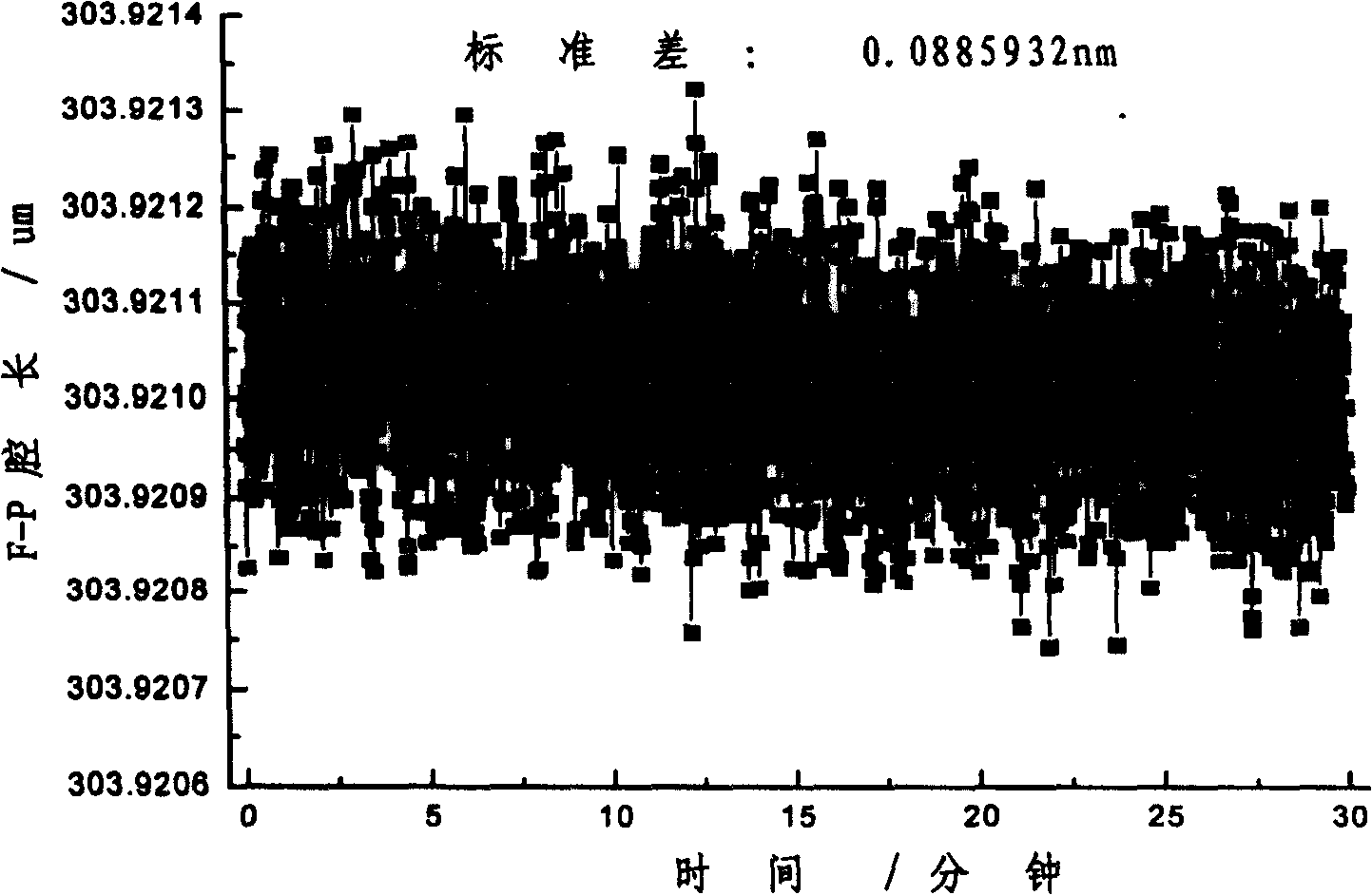
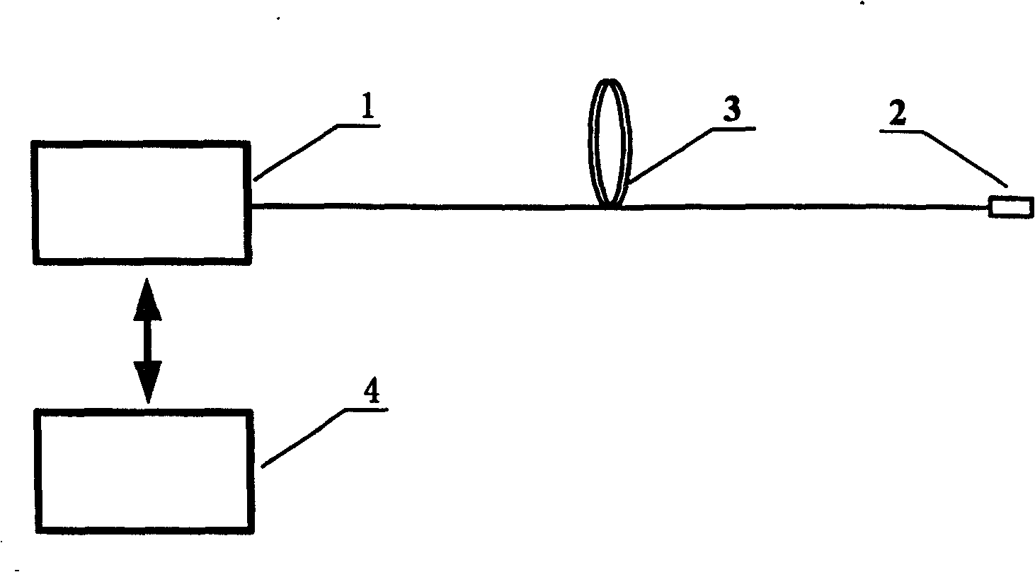
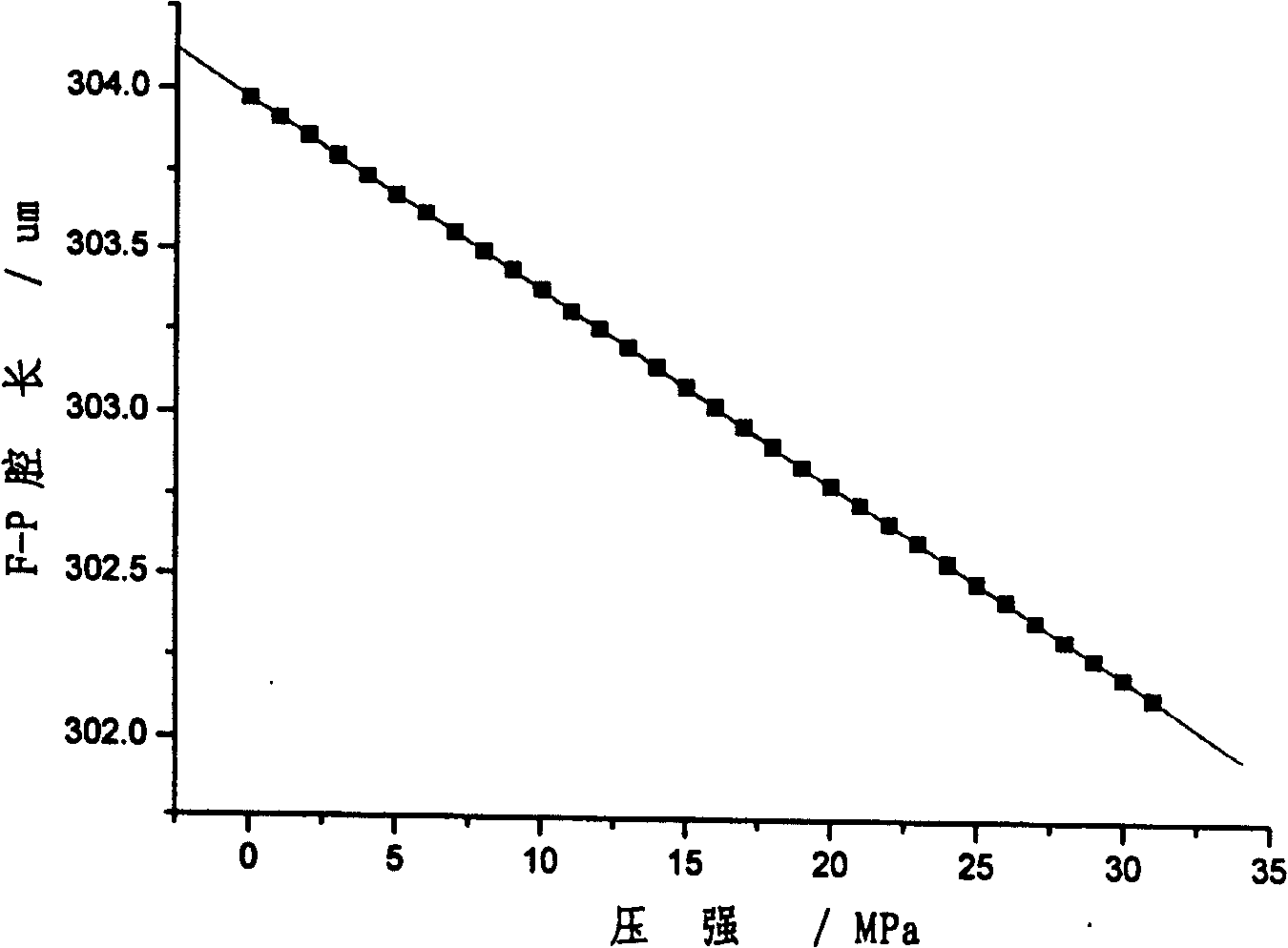

Image

  • Cavity length demodulating algorithm of fibre-optical F-P sensor
  • Cavity length demodulating algorithm of fibre-optical F-P sensor
  • Cavity length demodulating algorithm of fibre-optical F-P sensor

Examples


Embodiment Construction

[0024] The best embodiment of the present invention will be described in detail below in conjunction with technical solutions and accompanying drawings.

[0025] attached figure 2 An optical fiber F-P pressure measurement system suitable for downhole high pressure measurement is presented. The spectrum acquisition device in 1 here adopts SI720 of Micron Optics Inc., and its wavelength range is 1510-1590nm. The narrow-band light output from the scanning laser in the SI720 is transmitted to the extrinsic F-P sensor head 2 through the single-mode optical fiber 3. After the reflection spectrum is received by the SI720, it is sent to the computer through the communication interface, and the cavity length is determined by the demodulation program of the present invention. operation.

[0026] In the experiment, the DPI610 pressure calibrator of Druck Company was used to calibrate the optical fiber F-P sensor head in the range of 0-31MPa. attached image 3 The pressure calibratio...


PUM


Abstract

A demodulation ¿C algorithm of optical fiber F-P transducer cavity length includes calculating out a group of ideal spectrum sequence for reasonable estimation element according to transfer function of optical fiber F-P sensing head, calculating out a group of mean ¿C square error value according to calculated out ideal spectrum sequence and measured spectrum sequence, using estimation element corresponding to minimum mean ¿C square error as optimum estimation element of actual cavity length.

Description

technical field [0001] The invention belongs to the technical fields of optical fiber communication and optical fiber sensing. It relates to a general-purpose, high-precision wavelength demodulation optical fiber Fabry-Perot (F-P) sensor cavity length demodulation algorithm, in particular to the demodulation of F-P cavity optical fiber sensors in the field of optical fiber sensing technology algorithm. Background technique [0002] In 1988, Lee et al. successfully made the fiber-based intrinsic F-P sensor for the first time; in 1991, Murphy et al. developed an optical fiber sensor device based on the extrinsic F-P cavity. Due to the advantages of small size, simple structure, high sensitivity, flexible production, and no electromagnetic interference, the optical fiber F-P sensor head has been developed rapidly, and is widely used in sensing in harsh environments such as high temperature, high pressure, and strong electromagnetic interference. Measurements, such as health m...

Claims


Application Information

Patent Timeline
Patent Type & Authority Patents(China)
IPC IPC(8): G01D5/353G01D5/26H04B10/12H04B10/25
Inventor 宋世德于清旭
Owner DALIAN UNIV OF TECH
Learn More