


Quick Research
Generate reliable direction feasibility study reports for your R&D in just a few steps.

Technical Q&A
Discover and master advanced knowledge NOW. Basics, ideas, possibilities, all at once.

Find Solutions
As an expert in R&D theories, this can generate solutions to your technical problems instantly.

Evaluate Feasibility
Analyze your overall solution with one click, know your potential R&D risks in advance.

Monitor Landscape
Get weekly tech updates, stay abreast of the latest tech innovations and key insights.
Bistationary state electro magnetic valve
A solenoid valve, bistable technology, applied in the direction of valve details, multi-way valves, valve devices, etc., can solve the problems of complex valve core structure, short life, high energy consumption, etc., to achieve simple structure, long service life, energy saving The effect of energy consumption
- Summary
- Abstract
- Description
- Claims
- Application Information
AI Technical Summary
Problems solved by technology
Method used
Image

Examples
Embodiment 1
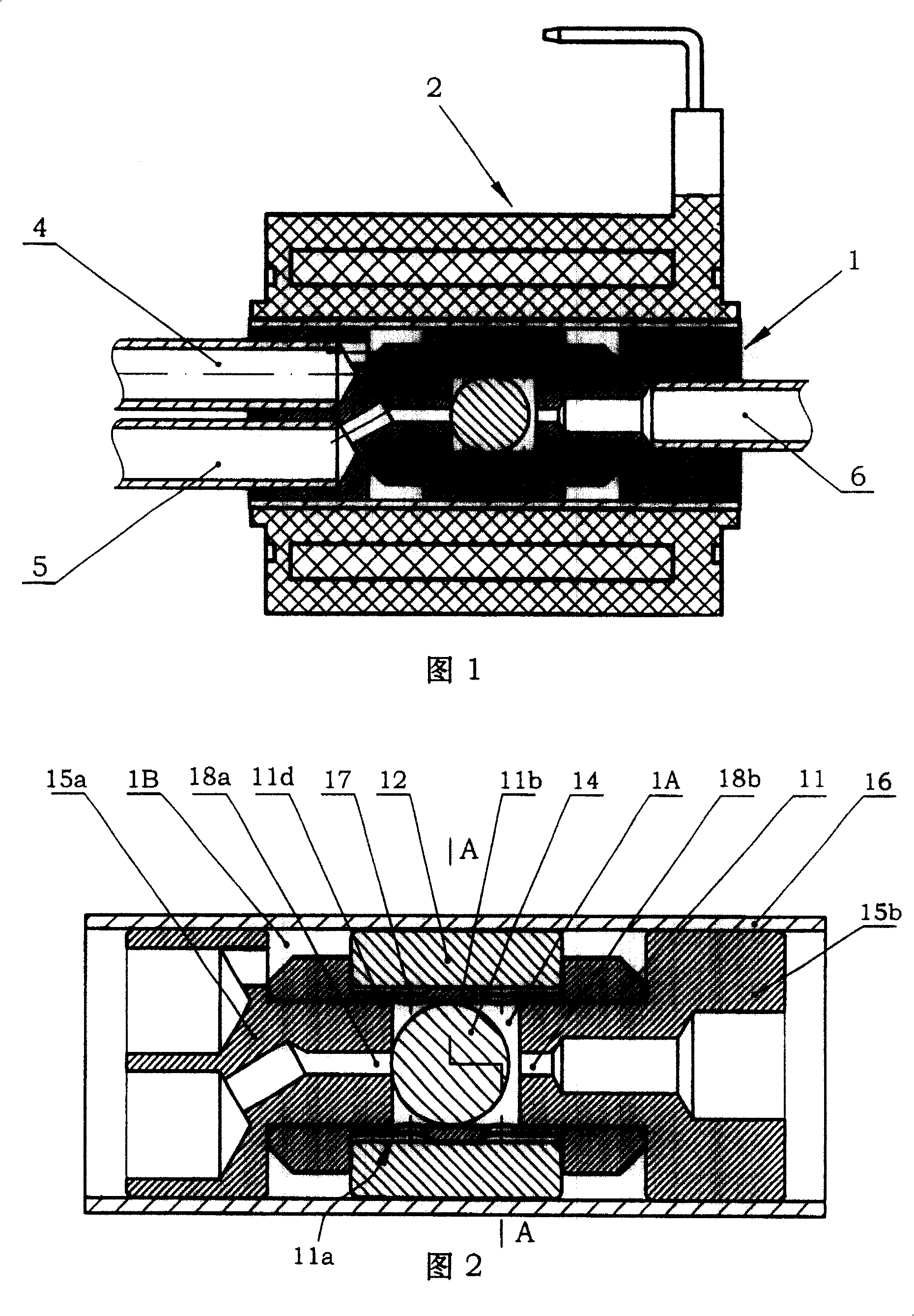
[0032] The solenoid valve shown in Figure 1 is composed of a valve body part 1, an inlet connecting pipe 4, two outlet connecting pipes 5 and 6, a control coil 2 and a coil housing 3, among which:
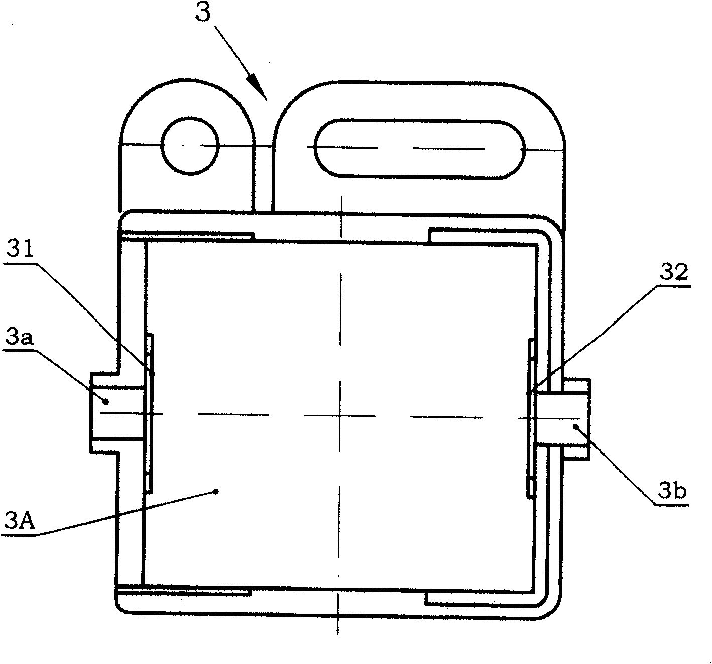
[0033] The control coil 2 is made into a structure with a through hole in the middle, and its external shape is convenient to be assembled in image 3 Inside the coil housing 3 shown.
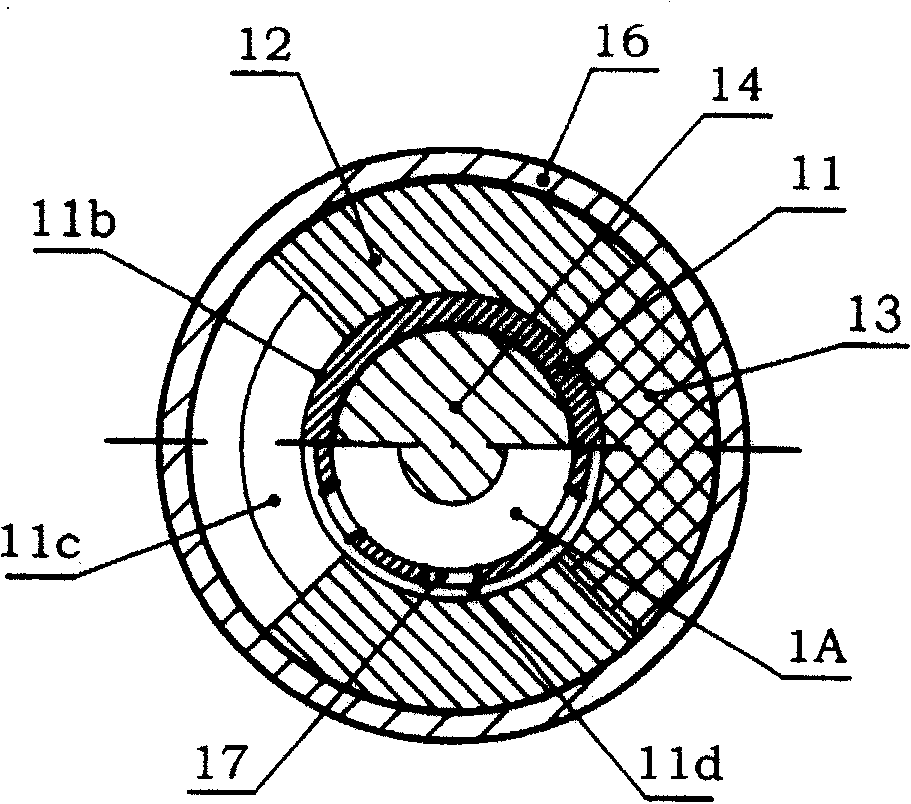
[0034] The valve body part 1 includes a sleeve 16 as a closed structure, a spacer as a tubular object 11, two sector ring magnets 12, a spacer 13, two valve seats 15a, 15b and a steel ball 14 as a valve core The casing 16 is a round pipe; the spacer is also a round pipe, its outer diameter is slightly smaller than the inner diameter of the casing, and there is an annular groove-shaped recessed part 11a in the middle of the outer surface of the pipe wall, and an annular protrusion 11b is arranged in the middle of the recessed part 11a , offer some through holes on both sides of the annular protrusion...
Embodiment 2
[0041] The bushing of Embodiment 1 can be omitted, and instead of opening a through hole in the recessed part of the spacer as the inlet, the inlet is directly opened on one of the valve seats and arranged in parallel with the outlet on the valve seat, while the control coil is directly installed On the core component described in Embodiment 1, a structure as disclosed in Patent No. ZL03271725.3 is formed, which can also achieve the technical effect of the solution, and will not be repeated here.
PUM
 Abstract
Description
Claims
Application Information
 - R&D Engineer
- R&D Manager
- IP Professional
- Industry Leading Data Capabilities
- Powerful AI technology
- Patent DNA Extraction
Browse by: Latest US Patents, China's latest patents, Technical Efficacy Thesaurus, Application Domain, Technology Topic, Popular Technical Reports.
© 2024 PatSnap. All rights reserved.Legal|Privacy policy|Modern Slavery Act Transparency Statement|Sitemap|About US| Contact US: help@patsnap.com