Permanent magnetism roller capable of generating fluctuation magnetic field

A permanent magnet and magnetic rolling technology, applied in the field of permanent magnetic rolling, can solve the problems of long action distance, not too far action distance, and not strong design, etc., to achieve long magnetic field action distance, high utilization rate of magnetic source, Meet the effect of treatment and rehabilitation

Inactive Publication Date: 2009-01-28
北京玛格涅磁应用技术有限责任公司 +1
View PDF0 Cites 0 Cited by
  • Summary
  • Abstract
  • Description
  • Claims
  • Application Information

AI Technical Summary

Problems solved by technology

[0005] 1. Since the magnetic field circulates in the cross-section perpendicular to the longitudinal axis of the magnetic roll, that is, the orientation direction of the permanent magnet source is limited within the cross-section of the magnetic roll, since the magnetic roll cannot be made too thick (the market needs magnetic roll is made slender), so the size of the magnetic source orientation direction can not exceed the cross-sectional diameter of the magnetic roll, the magnetic potential is limited, and cannot be designed very strong, which makes the ability of the permanent magnetic magnetic roll of the prior art to generate a magnetic field limited;
[0006] 2. The magnetic source of the magnetic roller in the prior art generates a magnetic field in the space around the magnetic roller, and the magnetic field has the same level of distribution around the magnetic roller. There is no emphasis, so the utilization rate of the magnetic source is not high. ;
[0007] 3. The magnetic source is special-shaped, generally cylindrical, and wire cutting is required in the manufacture, which increases the manufacturing cost of the magnetic roller
[0008] Due to the occurrence of the above problems, the magnetic field generated by the magnetic rollers of the prior art decays rapidly along the radial direction of the magnetic rollers, and the action distance cannot be too far, and the utilization efficiency of the magnetic source is not high. Therefore, the magnetic rollers of the prior art cannot meet the medical requirements. The personnel hope that the magnetic field generated by the magnetic roller will not decay too fast along the radial direction of the magnetic roller, and the working distance should be as far as possible.

Method used


Image

  • Permanent magnetism roller capable of generating fluctuation magnetic field
  • Permanent magnetism roller capable of generating fluctuation magnetic field
  • Permanent magnetism roller capable of generating fluctuation magnetic field

Examples


Embodiment

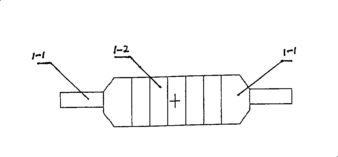
[0031] like Figure 4 Shown, a kind of permanent magnetic magnetic roller that produces variable magnetic field, it has shaft handle 4-1, permanent magnetic source 4-2, shell 4-3, non-magnetic coupling 4-4, motor 4-5 and non-magnetic Magnetic bearings 4-6;

[0032] The fastening strips on the shafts 4-1 at both ends fasten three quadrangular prism-shaped permanent magnetic sources 4-2 into a slender columnar structure;

[0033] The shaft at one end connects 4-1 with the motor 4-5 through the non-magnetic coupling 4-4; the shaft at the other end supports the 4-1 in the casing 4-3 through the non-magnetic bearing 4-6;

[0034] One side of the shell 4-3 can be opened, and the shaft 4-1 and the permanent magnet source 4-2 are installed together in the shell 4-3 made of non-magnetic conductive material, and are installed together in the shell 4-3. There are 4-5 drag motors, 4-4 non-magnetic couplings and 4-6 non-magnetic bearings;

[0035] Square prism shape permanent magnetic s...


PUM

PropertyMeasurementUnit
lengthaaaaaaaaaa
lengthaaaaaaaaaa

Abstract

The invention discloses a permanent magnetic roller for producing a variable magnetic field, which is suitable for magnetic recovery or the treatment of certain diseases. three permanent magnetic sources are fixed to be a slender structure by axle handles on two ends of the permanent magnetic roller; the axle handle on one end is arranged on a bearing; the axle handle on the other end is connected with a motor by a sleeve pipe and arranged inside a shell; the magnetization directions of the permanent magnetic sources positioned on the ends of two sides are vertical to the axis of the magnetic roller and have reverse orientations; the magnetization direction of the permanent magnetic source on the middle is the same as the axis of the magnetic roller; a magnetic field generated by the magnetic source circulates in the vertical section of the permanent magnetic roller; the field strength of the magnetic field generated outside the shell is far larger than the prior product; the permanent magnetic roller has small size and low cost and can meet the different requirements of clinical medical personnel.

Description

technical field [0001] The invention discloses a permanent magnetic roller generating a variable magnetic field, which is suitable for magnetic rehabilitation or the treatment of certain diseases, and belongs to the field of permanent magnet medical rehabilitation equipment. Background technique [0002] At present, the prior art has disclosed a class of permanent magnetic rollers that can generate a variable magnetic field. This magnetic roller is driven by a motor or manpower to rotate, and a magnetic field that changes with time is generated in the area around the magnetic roller. In recent years, it has been used For magnetic rehabilitation or the treatment of certain diseases; [0003] figure 1 Shown, is the typical structure schematic diagram of the permanent magnet magnetic roller of prior art, from figure 1 It can be seen in the figure that the two ends of the permanent magnet roller are shaft handles 1-1 made of non-magnetic materials, and the columnar permanent m...

Claims


Application Information

Patent Timeline
Patent Type & Authority Applications(China)
IPC IPC(8): H01F7/02H01F41/02A61N2/06A61N2/12
Inventor 胡振华
Owner 北京玛格涅磁应用技术有限责任公司
Why Eureka
Try Eureka