Signal transmission system and signal transmission line

A technology of signal transmission system and signal transmission line, applied in the field of signal transmission system

Active Publication Date: 2008-11-26
大冢宽治
View PDF7 Cites 1 Cited by
  • Summary
  • Abstract
  • Description
  • Claims
  • Application Information

AI Technical Summary

Problems solved by technology

However, transmission lines belong to the field of physics of electromagnetic phenomena, which is very different from the field including RC delays

Method used


Image

  • Signal transmission system and signal transmission line
  • Signal transmission system and signal transmission line
  • Signal transmission system and signal transmission line

Examples


Embodiment Construction

[0113] The present invention will be described in detail by referring to the accompanying drawings in conjunction with related embodiments.

[0114] In an embodiment of the present invention which will be described below, two circuit blocks are connected to each other by a differential signal transmission line of a simple structure on which a conventional single-ended signal is differentially transmitted, forming the circuit blocks shown in FIG. The transmission system 100 between circuit blocks is shown.

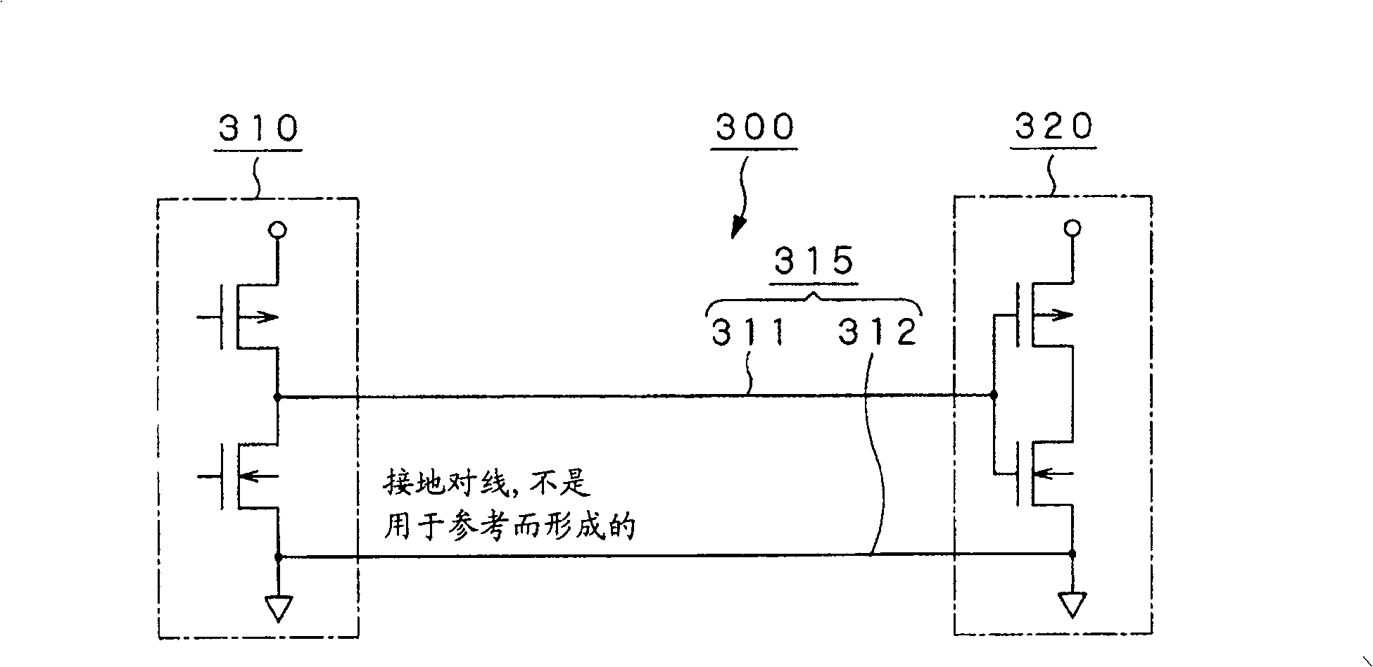
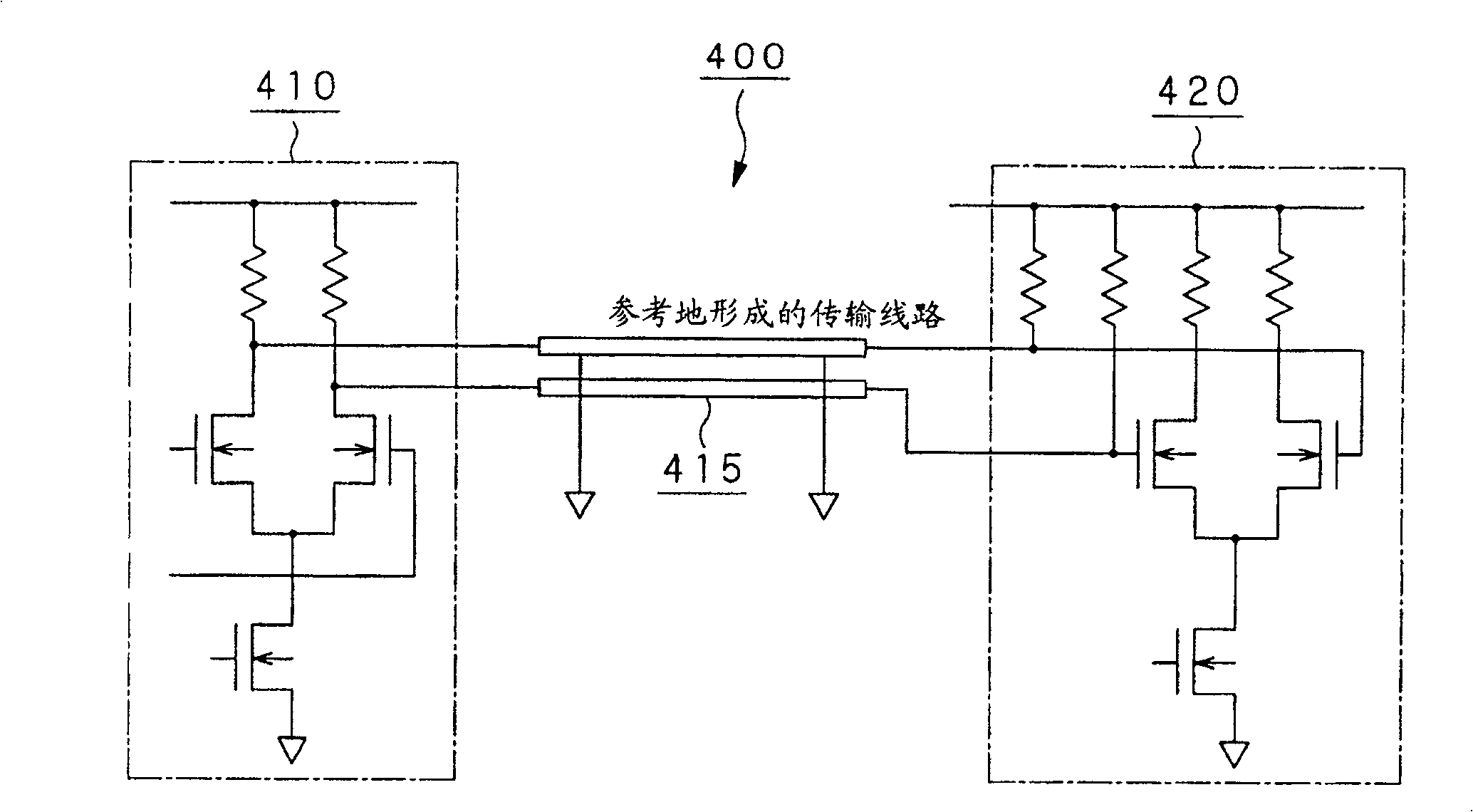
[0115] The inter-circuit block transmission system 100 includes two circuit blocks 10 and 20 connected to each other through a differential signal transmission line 30 and a power / ground pair transmission line 40 . Each of the circuit blocks 10 and 20 includes a functional circuit block 2 supplied with power from the power supply circuit block 1, an input / output circuit block 3 separated from the functional block 2, and an input / output terminal provided at the input / output ...


PUM


Abstract

To transmit a high-speed digital signal of several tens GHz via a differential line by connecting a differential line referring to the ground to differential lines not referring to the ground, there is provided a signal transmission system which transmits a digital signal between circuit blocks via a signal transmission line, each of the circuit blocks basically including a functional circuit, a reception / transmission circuit formed separately from the functional circuit and an impedance-matched transmission line(115)formed between reception and transmission ends of the reception / transmission circuit; a differential line(105)referring to the ground(110), led out from a differential output driver, being formed from differential signal lines disposed symmetrically with respect to the ground(110)in the circuit block, only differential pair lines(111, 112)not referring to the ground being extended directly from the differential signal lines disposed symmetrically with respect to the ground in the signal transmission line(115).

Description

technical field [0001] The present invention relates to a signal transmission system for transmitting digital signals between circuit blocks via a signal transmission line, and to a signal transmission line. Background technique [0002] For high-speed digital signal transmission from a CMOS differential driver to a receiver via a signal line, prior to the present invention, the inventors of the present invention proposed to treat a power / ground pair as a transmission line, and by forming a power line and a ground line, it The electromagnetic field is almost closed for the complementary signal energy provided to the driver. The power line and the ground line form a parallel pair of lines with equal lengths on the wiring circuit board, and its coupling coefficient is large (unpublished in Japan Examined Patent Application No. 284126, 1999 (will be referred to as Patent Document 1), and by providing a circuit for forcibly pumping in and pumping out required charges for state t...

Claims


Application Information

Patent Timeline
Patent Type & Authority Patents(China)
IPC IPC(8): G06F13/40H01P3/02G08C19/00H01P5/02H01P5/08H03K17/041H03K19/0175H04B3/02H04L25/02H04L25/08
CPCH03K17/04106H04L25/08G08C19/00
Inventor 大塚宽治宇佐美保
Owner 大冢宽治
Why Eureka
Try Eureka