
Method and device for removal of thin-film

A thin-film and radiation-oriented technology, which is applied in lasers, laser welding equipment, electrical components, etc., can solve the problem of expensive energy conversion efficiency of femtosecond laser oscillators and achieve the best results

Inactive Publication Date: 2008-07-16
HITACHI ZOSEN CORP +2
View PDF6 Cites 0 Cited by
  • Summary
  • Abstract
  • Description
  • Claims
  • Application Information

AI Technical Summary

Problems solved by technology

When using this laser oscillator, only the ITO layer can be removed; however, the femtosecond laser oscillator is expensive and the energy conversion efficiency is very low, that is, it is only still in the research stage

Method used


Image

  • Method and device for removal of thin-film
  • Method and device for removal of thin-film
  • Method and device for removal of thin-film

Examples


Embodiment Construction

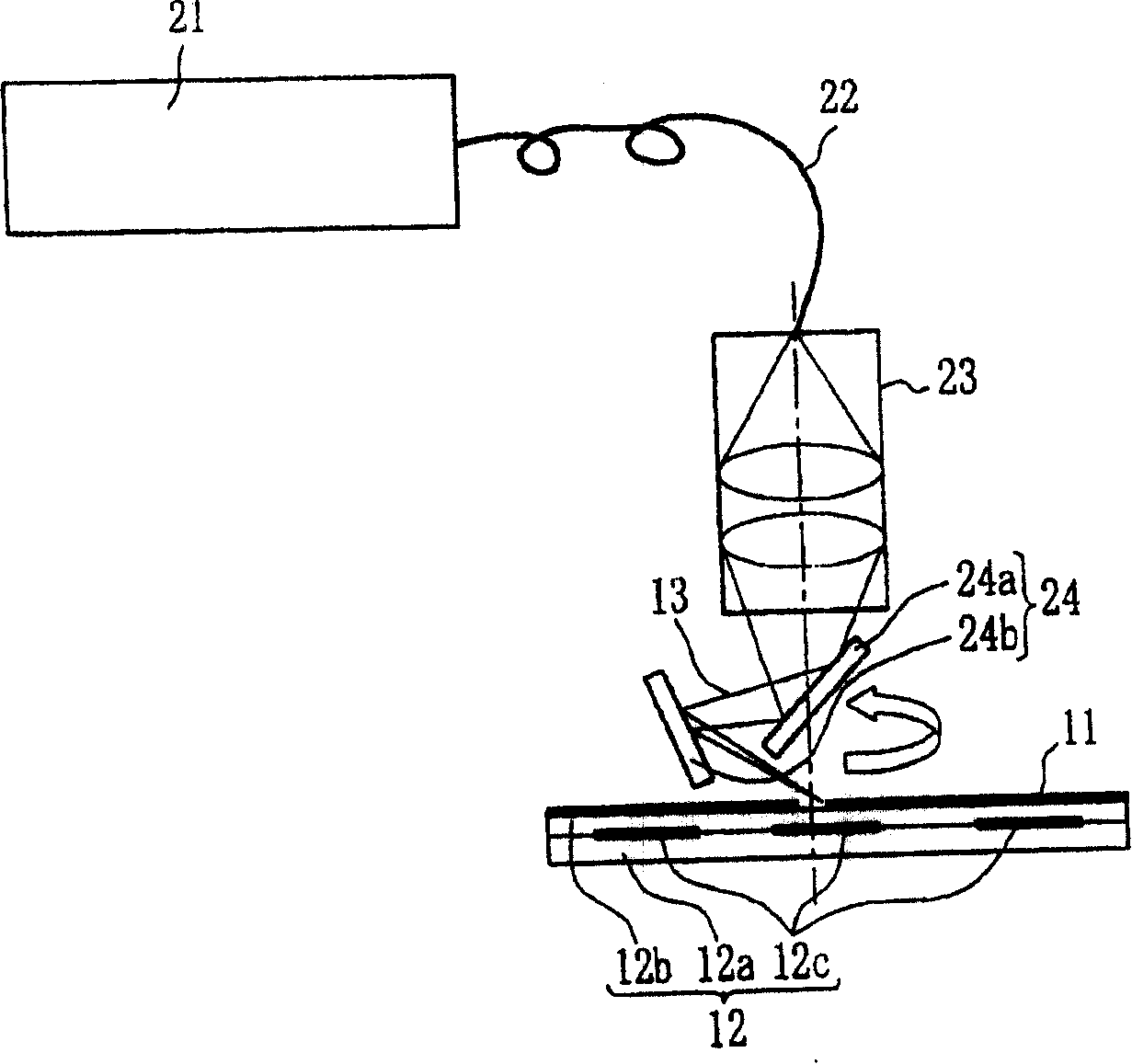
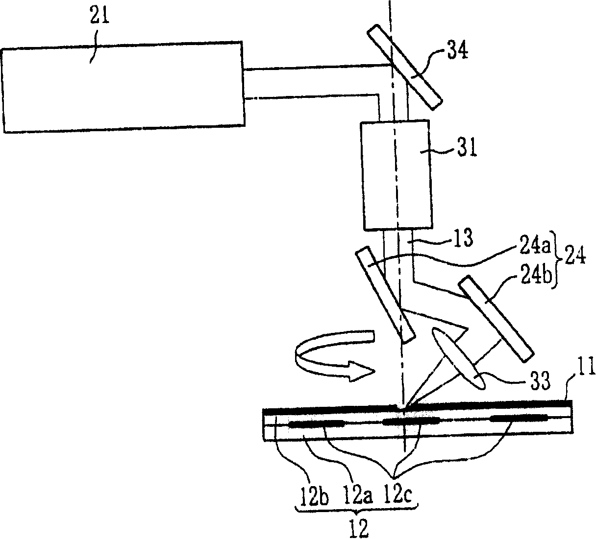
[0049] In order to illustrate the present invention in more detail, the accompanying figure 1 to 5.

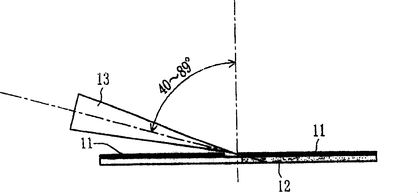
[0050] figure 1 is a schematic diagram illustrating a thin film removal method according to the present invention, such as figure 1 As shown, in the present invention, the top-hat energy distribution is generated by optical fiber transmission or an optical system with a uniform laser beam energy distribution function, so that the laser beam 13 with, for example, 1064 nanometers is irradiated on the substrate 12 made of acrylic layer, The thin film 11 that is coated with for example ITO layer or propylene layer, black matrix layer, glass layer etc. on this substrate surface is inclined 70 from the oblique direction relative to the surface of the substrate 12, such as from the vertical direction perpendicular to the surface of the substrate 12. ° direction with repeated irradiation at a frequency of 100 kHz.

[0051] In the thin film removal method according to the present...


PUM


Abstract

There is provided a method for removal of a thin-film, which removes a thin-film (11) from the surface of a substrate (12) by radiating laser beam (13) onto the surface of the substrate (12) coated with the thin-film (11). The laser beam (13) is radiated aslant onto the surface of the substrate (12).

Description

technical field [0001] The present invention relates to a method and apparatus for removing thin films on substrate surfaces using laser beams. Background technique [0002] The process of removing thin films using laser beams can be applied to thin film patterns formed in semiconductor thin films, thin film solar cells, liquid crystal panels, etc., or to organic EL (electron luminescent) displays and transparent multilayer thin film structure products, etc. In the method of removing a thin film using a laser beam, hitherto, the laser beam is vertically projected onto the substrate. [0003] In this case, in order not to exert harmful thermal influence on the substrate, (1) use a concentrating optical system with a very short focal length, (2) use a laser with a shorter wavelength, or (3) use a laser with a very short Use the laser beam for a period of time. In the methods (1) to (3), appropriate conditions for removing the thin film differ depending on the material, color...

Claims


Application Information

Patent Timeline
Patent Type & Authority Patents(China)
IPC IPC(8): B23K26/36B23K26/351B23K26/042B23K26/067B23K26/361H01S3/00
CPCB23K26/386B23K26/36B23K26/0608B23K26/067B23K26/0853B23K26/385B23K26/041B23K26/0604B23K26/042B23K26/389
Inventor 福田直晃北侧彰一加藤刚山田实武井健治谷本康范鹈饲育弘宗像昌树
Owner HITACHI ZOSEN CORP
Learn More