Electric cleaner

A vacuum cleaner, electric technology, applied in the direction of vacuum cleaners, suction filters, household appliances, etc., can solve the problems of large vacuum cleaners, clogged meshes, difficult to small, etc., achieve high suction power, reduce ventilation resistance, prevent suction and air volume Falling effect

Inactive Publication Date: 2008-07-09
HITACHI APPLIANCES INC
View PDF4 Cites 0 Cited by
  • Summary
  • Abstract
  • Description
  • Claims
  • Application Information

AI Technical Summary

Problems solved by technology

Because a cyclone separation chamber is used to collect the dust collecting part of the dust, all the large and small dust are collected together, so when the collected dust is poured out, the fine dust is easy to fly up, so that the dust is poured out. Operation is very troublesome
In addition, when the performance of collecting dust (dust collection) is to be improved, the length of the cyclone separation chamber must be lengthened, making the vacuum cleaner larger
[0005] The cyclone-type dust separation device (dust collection part) in which the cyclone separation chamber is arranged horizontally must be provided with a special flow path in order to generate a swirling air flow at the entrance of the cyclone separation chamber, so it is difficult to make a small and easy-to-operate form
In addition, since the filters on the side of the cyclone separation chamber and the side of the dust containing part are used separately, the meshes are quickly clogged, or if the filter area is not increased, it is difficult to improve the index indicating the ability to suck dust. suction power

Method used


Image

  • Electric cleaner
  • Electric cleaner
  • Electric cleaner

Examples


Embodiment 1

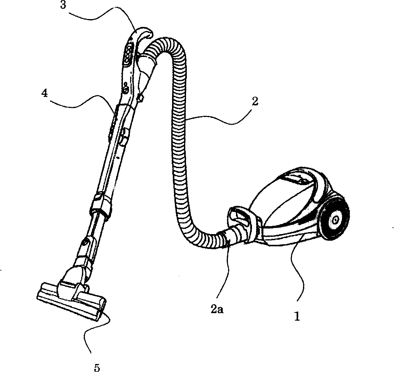
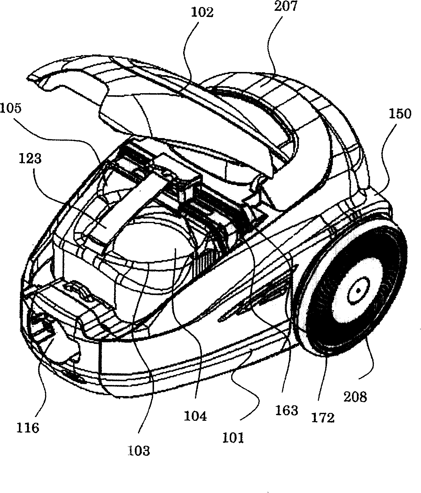
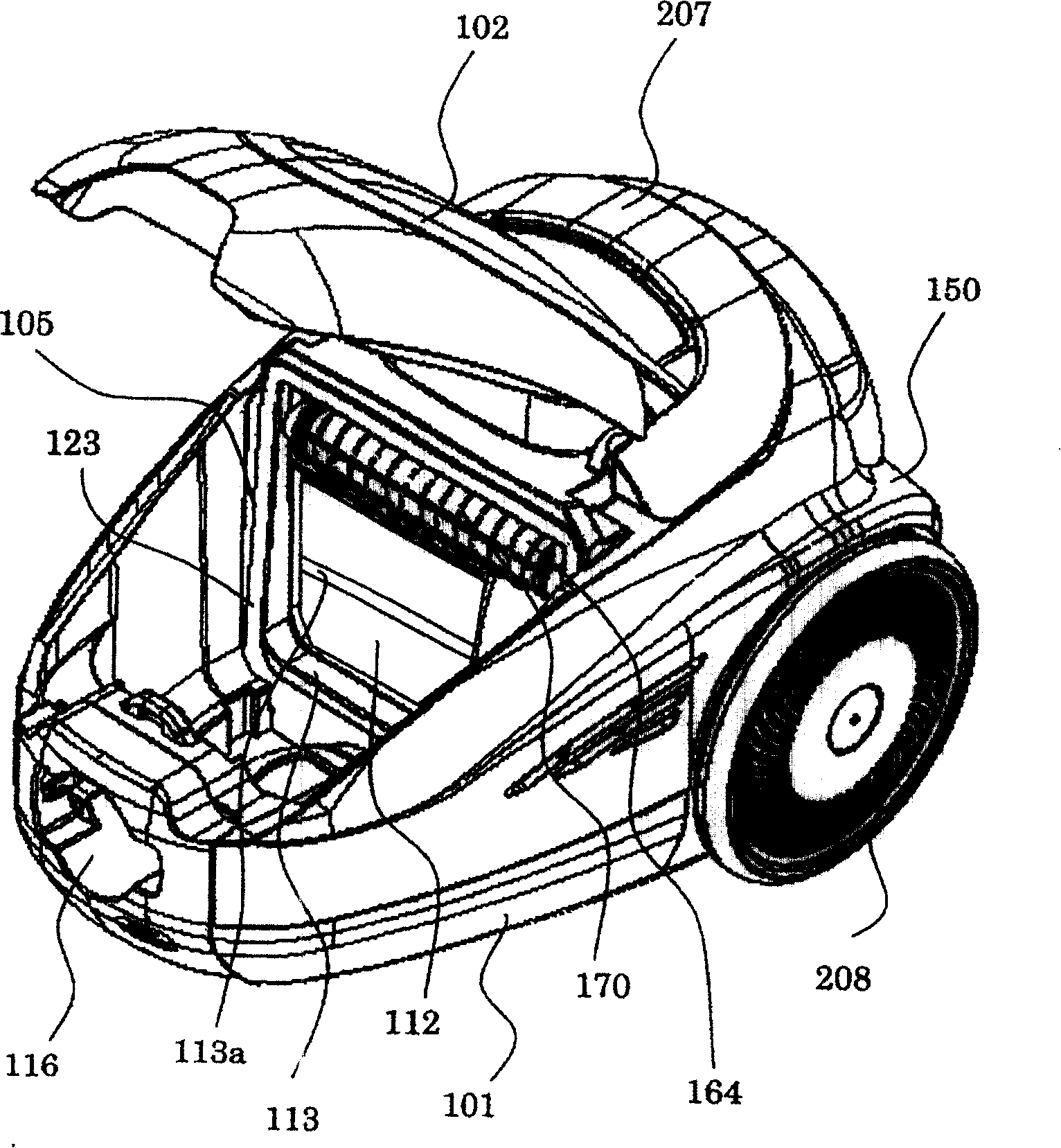
[0038] figure 1 It is a perspective view showing the appearance of an electric vacuum cleaner according to an embodiment of the present invention; figure 2 is a perspective view showing that the upper cover of the main body of the vacuum cleaner is in an open state; image 3 It is a perspective view showing the state where the dust collecting part 103 is detached by opening the upper cover of the main body of the vacuum cleaner; Figure 4 is a schematic diagram showing the air flow in the main body of the vacuum cleaner; Figure 5 is a three-dimensional view of the appearance of the dust collection part 103; Figure 6 is an external perspective view of the dust collection part 103 seen from the downstream side; Figure 7 It is an appearance perspective view after opening the filter frame 140 and the filter frame 163 together from the dust collecting case 105; Figure 8 is a longitudinal sectional view of the dust collection part 103 including the central axis of the inner...


PUM


Abstract

The invention discloses an electric cleaner with small-sized and operational cyclone separating dust collection part, which comprises the following parts: inflow part (115) to flow air with dust, separating chamber (104) to separate dust in the air, first dust containing part (105a) to contain dust from separating chamber, first interconnecting hole (117) to connect the first dust containing part and separating chamber, first vent (144) to drain air from separating chamber, second vent (146) at the position of first dust containing part, second dust containing part (105b) to contain dust away from the first dust containing part (105a), second connecting hole (118) to connect second dust containing part and separating chamber at the position of first connecting hole, third vent (147) to drain air out of the second dust containing part.

Description

technical field [0001] The present invention relates to electric vacuum cleaners. Background technique [0002] The structure of the usual electric vacuum cleaner is to introduce the dust-containing air inhaled from the suction hole into the main body of the vacuum cleaner, collect the dust through the dust collecting part in the main body of the vacuum cleaner, and discharge the clean air from which the dust has been removed to the vacuum cleaner. The outside of the main body of the vacuum cleaner goes. The structure of the dust collection part is to filter by means of a paper filter to collect the dust, or to capture and collect the dust by means of centrifugal separation in the cyclone separation chamber. [0003] The dust collecting part of the cyclone type electric vacuum cleaner is, for example, that described in Patent Document 1 (Japanese Patent Laid-Open No. 2003-79546). In this structure, the dust collecting part of the cyclone-separated electric vacuum cleaner s...

Claims


Application Information

Patent Timeline
Patent Type & Authority Patents(China)
IPC IPC(8): A47L5/12A47L9/10
Inventor 林正二岩濑幸司铃木龙路伊藤则和庭濑好夫菅野恭一
Owner HITACHI APPLIANCES INC
Why Eureka
Try Eureka