
Linkage type handle and foot stool electronic device

An electronic device and handle technology, which is applied in the directions of support structure installation, electrical digital data processing, instruments, etc., can solve the problems of inconvenience, inconvenience, and increased weight, etc.

Inactive Publication Date: 2008-06-25
王雯雯
View PDF2 Cites 0 Cited by
  • Summary
  • Abstract
  • Description
  • Claims
  • Application Information

AI Technical Summary

Problems solved by technology

[0005] Generally speaking, most of the information products sold by various designers and manufacturers in the market do not have a design leader to facilitate the user to move them. Therefore, when the user must move the information product, it seems rather inconvenient
[0006] Even if these information products have the design of the handle, they are all of a fixed design, which is either not aesthetically pleasing, or inconvenient to use or easy to hurt the user's hands, etc...
[0007] Furthermore, most of the tripod designs of these information products are also fixed. In order to make these information products stable, the base usually needs to increase the area and weight. Inconvenience when transporting
[0008] In addition, the above-mentioned handle and the tripod are designed independently of the two structures, so the two cannot be related, and it is easy to cause the user to be affected and restricted during transportation. Users often can only silently accept the convenience of operation and aesthetic appearance of information products during transportation.

Method used


Image

  • Linkage type handle and foot stool electronic device
  • Linkage type handle and foot stool electronic device
  • Linkage type handle and foot stool electronic device

Examples


Embodiment Construction

[0028] In order to make the purpose of the present invention, shape, structure device features and its effect easier to recognize and understand, the embodiments are given in conjunction with the drawings, and the detailed description is as follows:

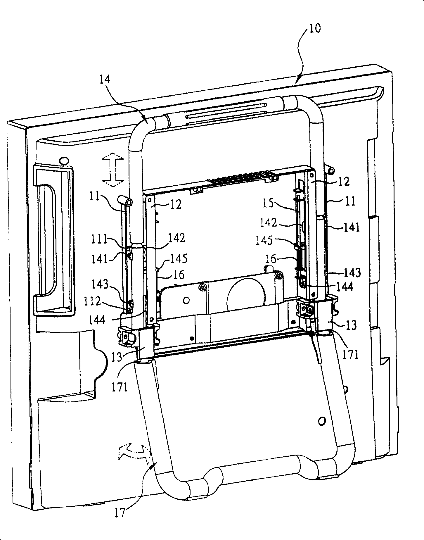
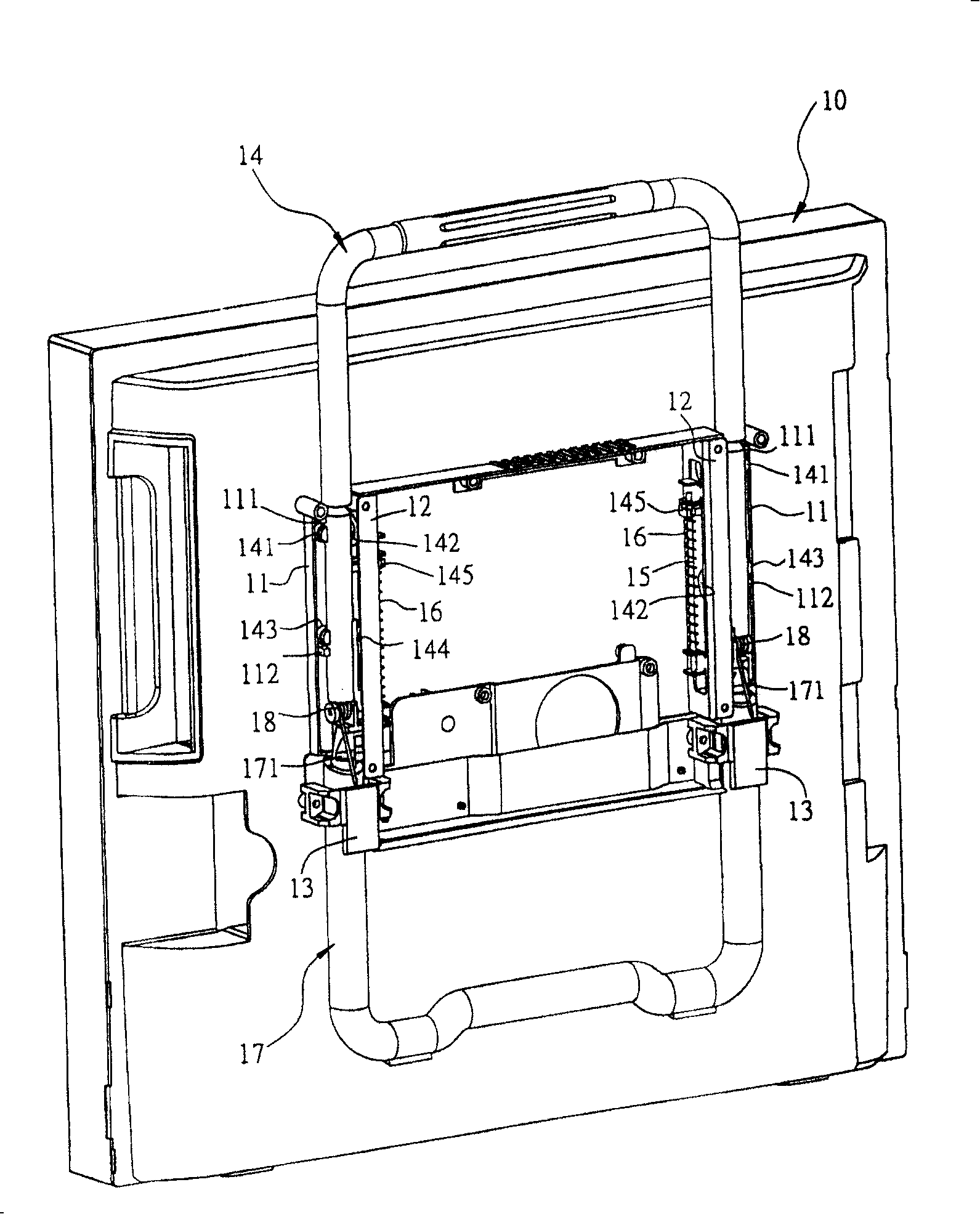
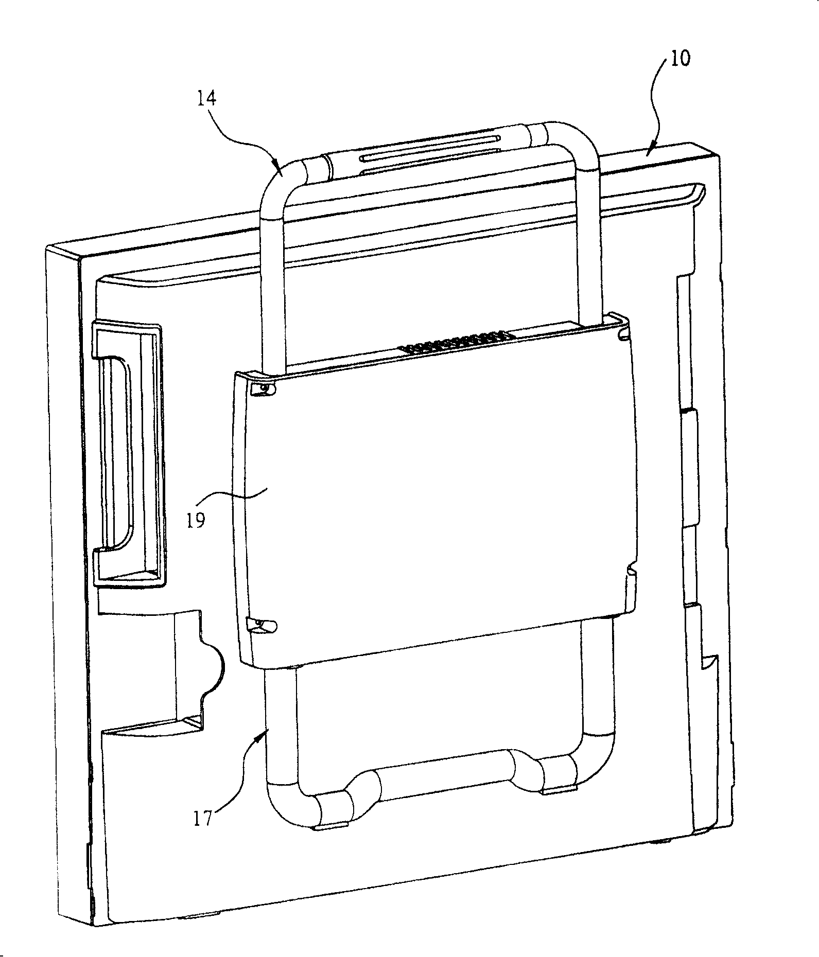
[0029] The present invention is an "electronic device with linked handle and tripod", please refer to figure 1 , figure 2 As shown, the electronic device is a liquid crystal display computer (LCD-PC) in the implementation of the present invention, which at least includes the following components, a body 10, and the back side of the body 10 is respectively provided with Two first slide rails 11 separated by a predetermined distance are respectively provided with two second slide rails 12 separated by a predetermined distance between two corresponding sides of the two first slide rails 11, wherein each of the second slide rails 12 is respectively There is a certain distance from each of the first sliding rails 11; the electronic ...


PUM


Abstract

The invention is an electronic device with linkage handle and stand, separately arranging two first slides and two second slides on a machine body, separately containing two extension rod bodies of an inverted U-shaped handle between every first and second slides, each rod body of the handle is separately provided with multiple trolleys and a first stopper; two ends of each second slide are each provided with a support rod respectively, each support rod penetrates through corresponding first stopper, and is jacketed with a spring; two extension rod body ends of the handle are each pin-jointed with two extension rod body ends of a U-shaped stand by a spring rotation shaft, respectively, the extension rod body ends of each stand are each provided with a notch adjacent to corresponding spring rotation shaft, respectively, the position adjacent to each spring rotation shaft is separately jacketed with a second stopper, each second stopper can be inserted into each notch at the extension rod body ends of the stand; when the handle is pressed down, making two extension rod body ends of the stand extend out to automatically spring at an angle and each notch on the stand will be inserted into the corresponding second stopper so as to form a support stand for the machine body.

Description

technical field [0001] The present invention relates to a design of interlocking handle and tripod, especially a kind of interlocking handle and tripod used on the back of an electronic device (such as: liquid crystal display computer, etc...), so that when in use , it is convenient for a user to grab the handle and lift the electronic device; when not in use, the handle can be pressed back, and the stand will automatically pop up to support the electronic device, so as not to affect its appearance Aesthetics and ease of operation. Background technique [0002] With the continuous innovation of various information products on the market, such as screens, TVs, desktop computers, tablet computers and liquid crystal display computers (LCD-PC), especially the wide application of personal computer systems (PCs) , People's requirements for the use of computers have also increased relatively. It is undeniable that whether computers in the future can provide more convenient and eff...

Claims


Application Information

Patent Timeline
Patent Type & Authority Patents(China)
IPC IPC(8): G06F1/16H05K7/14
Inventor 张绮棻王惠真田凯诚赖淑华陈建全吴汉顺
Owner 王雯雯
Learn More