Polluted fluid purifying method and system
A fluid purification and fluid volume technology, applied in chemical instruments and methods, separation methods, anaerobic digestion treatment, etc., can solve the problems of complicated production process, limited application scope, complicated production methods of porous carriers, etc.
- Summary
- Abstract
- Description
- Claims
- Application Information
AI Technical Summary
Problems solved by technology
Method used
Image

Examples
Embodiment 1
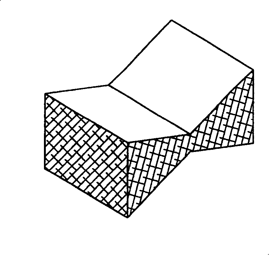
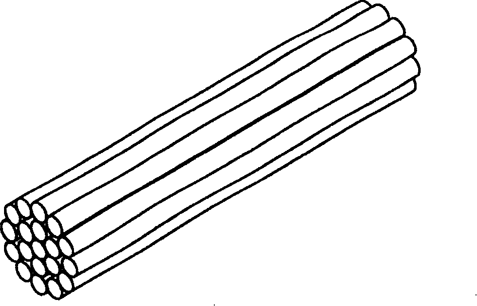
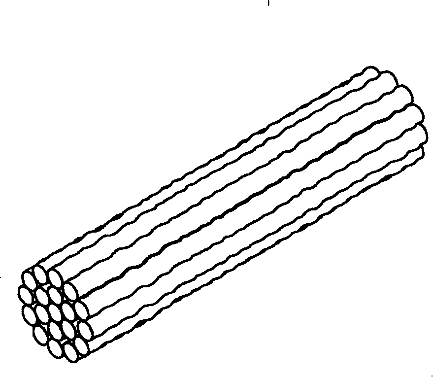
[0059] [Example 1] Production of a block-shaped nonwoven fabric having a central anchor line
[0060] Using polypropylene / polyethylene core-sheath composite fiber (manufactured by Taiwan Far East Textile Co., Ltd., product name SP-2650EP, fiber fineness of 6 denier, length of 5.1 cm) as raw material, this composite fiber was opened, cleaned After cotton, carding and stacking are processed, a fiber web layer is formed, and then the fiber web layer is subjected to the first fixing treatment of needle rolling and hot air processing, so that the fibers in the fiber web layer form a three-dimensional space bond to form a fibrous web layer. Nonwoven rolls with a basis weight of 500 kg / m² and a width of 1.8 m. The non-woven roll is then cut into a non-woven roll with a width of 0.6 meters, and then the non-woven roll is transported in the machine direction (that is, the longitudinal direction of the non-woven roll), and is subjected to a second fixing treatment The ultrasonic bondin...
Embodiment 2
[0061] [Example 2] Wastewater purification system using the block nonwoven fabric of Example 1
[0062] like Figure 12 As shown, the wastewater purification system 4 is a system for treating wastewater, and the wastewater purification system 4 includes a tank body 41 for containing wastewater and a volume of 500 liters, placed in the tank body 41 and obtained by the Example 1. A block-shaped nonwoven fabric 42 having a central anchor line, a spacer 43 and two diffusers 44. The tank body 41 has a waste water outlet 411 and a waste water inlet 412 opposite to and staggered from the waste water outlet 411 . The isolation device 43 is disposed in the tank body 41 and close to the waste water inlet 412, and is composed of a porous plate body. The two diffusing devices 44 are respectively disposed on both sides of the tank body 41 and have a plurality of holes 441 for gas to escape, so that the block-shaped non-woven fabric 42 can be fully mixed with the waste water.
[0063] Th...
Embodiment 3
[0068] [Example 3] Wastewater purification system using activated sludge-grown bulk nonwoven fabric
[0069] The block non-woven fabric obtained in Example 1 was subjected to the following activated sludge planting process: collecting the sludge in the waste water recovery tank of the laundry factory, this sludge is the so-called "activated sludge", and then the sludge was collected. The sludge and an appropriate amount of water are put into the treatment tank, and then the block non-woven fabric of Example 1 in the amount to be used is put into the treatment tank for about 8 hours to obtain the activated sludge planted block-shaped nonwoven fabric. spinning.
[0070] Utilize the wastewater purification system of Example 2, and purify according to the same method of Example 2, but replace the block nonwoven fabric 42 of Example 2 with the block nonwoven fabric planted by activated sludge, Finally, after the same 12 hours, water samples were taken at the inlet and outlet of th...
PUM
| Property | Measurement | Unit |
|---|---|---|
| length | aaaaa | aaaaa |
Abstract
Description
Claims
Application Information
 - Generate Ideas
- Intellectual Property
- Life Sciences
- Materials
- Tech Scout
- Unparalleled Data Quality
- Higher Quality Content
- 60% Fewer Hallucinations
Browse by: Latest US Patents, China's latest patents, Technical Efficacy Thesaurus, Application Domain, Technology Topic, Popular Technical Reports.
© 2025 PatSnap. All rights reserved.Legal|Privacy policy|Modern Slavery Act Transparency Statement|Sitemap|About US| Contact US: help@patsnap.com